My setup keeps track of my grid electricity and gas usage thanks to a smart meter, solar via a couple of raspberry Pi, and water thanks to the fact that water meters broadcast their reading unencrypted!
Electricity and Gas
I finally relented last year and got a smart meter. My electricity is with British Gas and they rather cheekily just booked a meter replacement appointment without me asking. I decided to keep it rather than cancelling it as I’m a sucker for tech! I was put off because my existing meter would actually run backwards if I was generating more than I was using.
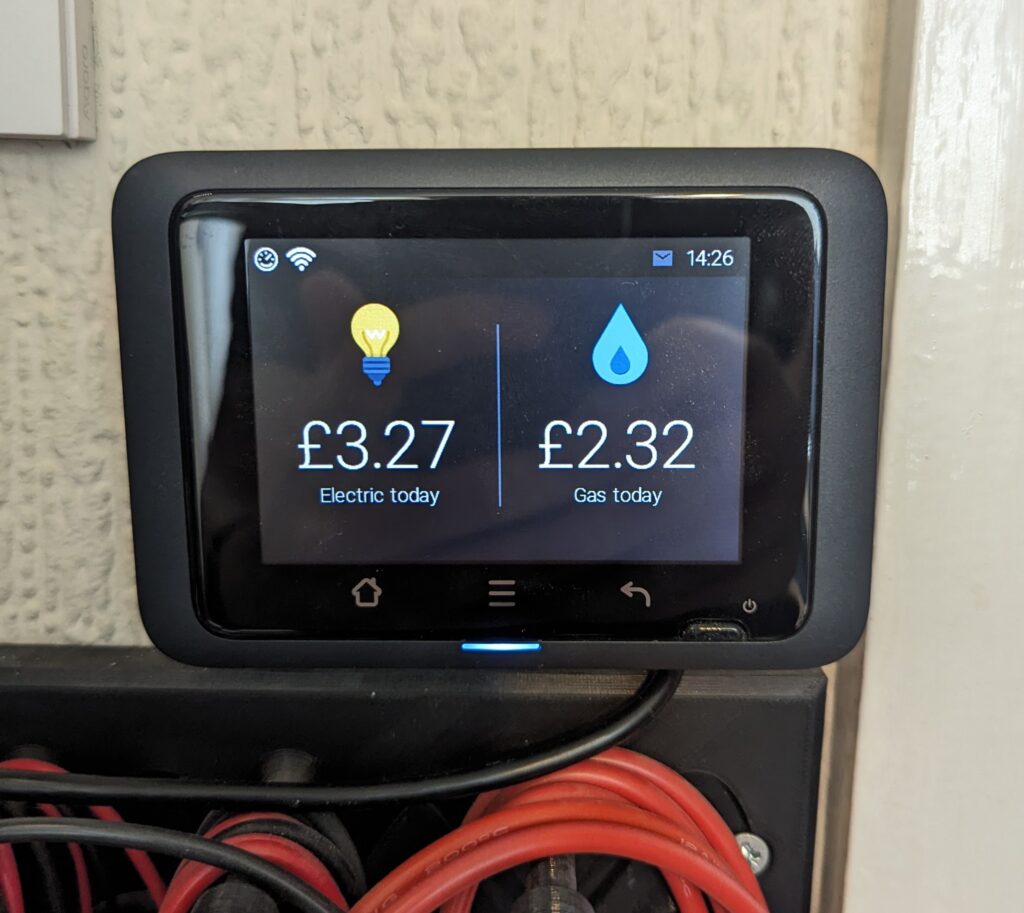
With the meter installed, it comes with a readout to show you how much you are currently using. Its not quite straight forward to get the details into Home Assistant. You can sign up on an app called Bright and get half hourly meter readings for free, and this has an integration built into Home Assistant. This is a nice quick way of getting the data but it isn’t very granular.
Alternatively you can get a different display from Hildebrand that not only will read your meter for instantaneous data, but also connects to your wifi and provides data via an MQTT connection to Home Assistant, with an associated integration.
Once connected, you can add the relevant entities into the Energy dashboard.
Solar

I have two relatively small grid tied solar installs (limited by the amount of roof space), one on the garage and one on the main roof both using Solis inverters. The problem with these inverters is that the default method of logging the data writes all the info off to a third party in China. Now I’m not necessarily a security nut, but I do like to avoid cloud based services wherever possible.
Thankfully, the logging stick that comes with the inverter actually just reads RS485 (modbus) registers. After much trial and error due to lack of decent documentation (or more to the point, documentation that actually agrees!) I managed to write a python script which reads the registers and posts the data to MQTT using the Home Assistant auto discovery layout.
This script is running on a PiZeroW, using the connector off the standard logging stick. I did ask if they had any broken sticks to save wasting a working one, throwing away all the electronics.
Water
The last bit of the puzzle for my house was a bit of a long shot. When we moved in we decided to go with a water meter due to the rates for our area being way too high. I didn’t think much of it, but as I now had a smart meter for gas and electric, plus all the solar being logged into Home Assistant, I thought I’d take a look. The fact that the Energy dashboard had a section for water definitely had a influence!
After wiping off a rather thick layer of dust from the meter, I got the model number and started looking things up about it. Turns out it broadcasts the meter reading on a standard 868Mhz, which of course can be listened in on using a simple, cheap USB digital TV dongle. I may have a few of them laying around the house (including one listening in to all the planes passing overhead). Even better, it was unencrypted.
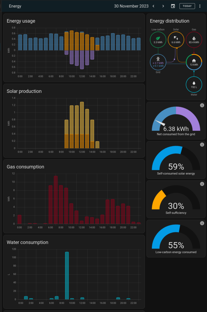
Thankfully I didn’t have to write everything myself, there is already an open source program call wmbusmeters that will use an RTL dongle and output the data in JSON to the stdout. With a quick python wrapper to read that data and post it via MQTT for Home Assistant to read (again, using the auto discovery layout)
Energy Dashboard
All the entities created are then entered into the relevant sections in the Energy Dashboard. This automatically configures everything to display and record the information. It gives a nice page to view all the data. I’ve also got a number of devices hooked up with plug in energy meters so I can see the consumption of things like my server rack, computer, tv, etc. All of these will also get displayed on the dashboard.
Along with the dashboard, I also have graphs in Grafana for more granular details and spotting trends.
Future
At some point I want to possibly get a battery for the house. Once I’ve collected a year or so of data I’ll have a much better idea on the suitable size to get and should be able to calculate a fairly accurate ROI. For now I’m just happy to keep track of the energy usage.
]]>I also added a few new integrations:
- DVLA Link – This lets me query details about our cars, and more specifically the due dates for MOT and insurance.
- Waste Management – Link into the local government to know when and what type of refuse collection is coming up.
But, the most fun one was finally getting the 10 inch display and Raspberry Pi mounted on the wall as a custom control panel!
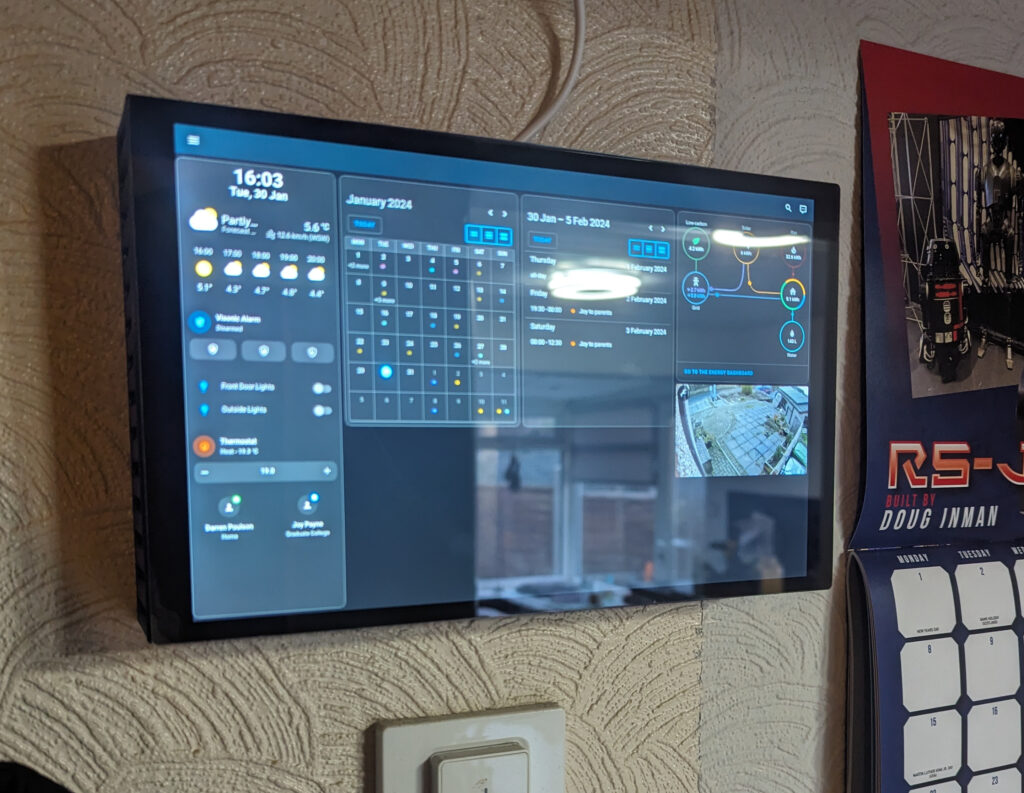
I’ve had it sat on my desk for about six months and decided it was actually time to get it done. I had to CAD up a box for wall mounting and hiding the electronics. Not the best design, and lots of things to improve, but its functional.
A quick couple of holes in the wall, and it was mounted.
Once I have the local voice assistant details finished, this will get that installed too. That will need a redesign of the case to support some speakers and volume controls. The actual dashboard needs a bit more work, and possibly an LCARS theme as an option.
But at least its off my desk and working now. Very handy for a quick glance at the calendar, weather, alarm status, and also to view the front door camera.
]]>Home Assistant has been around for a while, but I was loathe to move from OpenHAB as I already had a lot set up. However, as OpenHAB fell behind I finally bit the bullet and installed HAOS on a spare Raspberry Pi. This turned out to be a good thing.
I’ve been using it now for a couple of years, and it works really well as a central hub for all the different technologies in the house. This post is a quick overview of what I have set up.
Technologies
The beauty of Home Assistant is that it acts as a hub for many different home automation protocols, devices, and other information. A quick list of technologies I have integrated:
- Zigbee
- Z-wave
- ESPHome
- Matter
- Thread
- MQTT
- WLED
But not only does it talk to these home automation systems, it can also tie into other things such as:
- 3d Printers (Octoprint, Klipper, Bambu Labs)
- Google Assistant (Ties your home automation into google voice commands)
- Jellyfin/Plex
- Fitbit
- Raspberry Pi
- Roomba
- Smart Meters
- Printers (you know, the none 3d kind)
- Frigate (CCTV)
- Solar Production
And lastly, you can pull in information from web APIs to help with automations:
- Weather
- Sunrise/Sunset
- Moon phases
- Astronomy Weather (More detailed weather more geared to astronomers)
- Github (Monitor commits, issues, etc.)
- Whois (Keep an eye on domains expiring)
- DVLA (MOT and insurance due dates)
- Waste Management (get dates and types of refuse collection)
This is a lot of tech, and this isn’t a complete list of everything I have tied in, just the majority.
My Setup

So, enough of what it can talk to. How is my house set up?
Core
The main core of the system is a Raspberry Pi 4 running Home Assistant OS. This is a simple install onto a Pi and is fully managed by Home Assistant. Everything runs in containers and gives you everything you need to get started.
The Pi is run from PoE in a rack, to keep things simple, and also has everything installed onto an SSD drive as it is a lot more reliable that using an SD Card (My old OpenHAB system was on SD Card and I had to rebuild it every now and again as the SD card wore out). Plugged into the Pi are two USB dongles, one for z-wave and one for Zigbee/Matter. This direct connection lets me control the majority of the devices I have.
Also, installed as part of HA OS I have a few other addons. These are:
- InfluxDB – This keeps a historical record of all the stats in the house, which can then be pulled out into a Grafana Dashboard
- Mosquitto MQTT Broker – Some devices talk directly to an MQTT server, so this is running to fill that role
- ESPHome – A system designed to convert simple ESP32 or ESP8266 boards into home automation devices using a simple yaml language. Some commercial devices can also be flashed with ESPHome for extra functionality.
- HA Google Backup – Backups!!
- Lets Encrypt – Automatically renews my SSL cert
- VaultWarden – A locally run version of Bitwarden password manager.
These are all running on the same Pi quite happily.
CCTV (Frigate)
I have a second Pi 4 running a system called Frigate. This is an open source CCTV system that integrates really nicely with Home Assistant. It also has functionality for not only motion detection but facial detection too so that it will only trigger if it detects a human (not a cat or squirrel) which definitely helps cut down on false positives. I have had to block out certain areas for detection tho, as in high winds it sometimes thought some of Joy’s flowers were a human!
I’m hoping to upgrade this to a Pi 5 when the PoE hat comes out, as I currently have 4 cameras going into it and it does struggle a bit. I do have a USB Coral AI stick from Google that I can offload some of the more AI related tasks too.
NAS (TrueNAS Scale)
I do have a NAS box set up that has a simplified Kubernetes system installed. On this I run a few other services, including Grafana for viewing stats of my home, Spoolman which keeps track of my 3d printer filament usage, and Trilium Notes for keeping track of the random things in my brain.
Other Hardware
So what have I actually got set up?
Most of the main lighting in the house are Phillips Hue lights, with their dimmer controllers. However, since realising just how much data the Hue hub was sending back, I removed that and now everything is directly controller via Zigbee. The only main exception to this is the garage which initially had fluorescent tubes and I use a z-wave in wall module to control that.
I’ve a lot of smart sockets around the house too, from plugin units to actual in wall faceplates. The vast majority of these allow for energy usage collection too so I can not only turn things on and off remotely, but I can also monitor the energy usage of various items such as 3d printers, server cabinets, desktops, TVs, etc.
The burglar alarm is also connected in, which turns all the various door and motion sensors into sensors that Home Assistant can use for automations.
WLED is a system to install onto an ESP8266 or ESP32 to control a string of RGB LEDs. I’m starting to incorporate more of these into the setup and they tie very nicely into Home Assistant
Control

What does all this gain me? The main benefit is a single app on my phone to control everything. I don’t need a Hue app, a Roomba app, to access a webpage to control my WLED lights, etc. I can create a dashboard on Home Assistant to give me a nice overview of the controls in the house. For instance, my setup main dashboard consists of an overview page (simple controls such as lights, along with main thermostat control and some other status) with the ability to click a room and get more detailed controls and information. That covers about 90% of everything.
Along with this, as I have Google Assistant integrated, I can also just ask google to turn lights on, set the thermostat, etc.
Automations
So far, most of the stuff is just allowing for remote control, but the real beauty is making things automatic. I’ve only really got some basic automations done at the moment and want to expand on this in the future.
- Automatic outside lights. I have the lights set to come on at sunset, and turn off at midnight. They’ll also come on in the morning if Joy is going to work and its still dark out.
- Turn the thermostat down at night. The thermostat will drop a couple of degrees at midnight whilst we’re asleep to save some energy. I have got the alternative set to turn it back up in the morning, but thats disabled for now as its just as easy to turn it up manually depending on what time we get up.
- Send an alert if someone comes to the front door, and turn the light on. This is one of the reasons I want to upgrade the Frigate Pi. The Pi 4 is just a little slow on this, and hoping the extra processing power will speed things up.
- Show video feed on my google home displays when someone is detected on the front door camera.
- Automatic office lights. I’m terrible at remembering to turn my light off in the office, so I have a simple motion detector to automatically turn the lights on and off. They do turn off occasionally if I’m in the office concentrating on something and not moving much (such as writing a blog post about my home automation system) so I’ve just ordered some mm wave detectors to try which should be more sensitive.
- Notifications when prints have finished or theres an issue.
- Daily notification if a battery is low in a device. All my Phillips Hue Dimmers were bought at the same time, and I’ve just had to replace all the batteries at once!
Theres room to do a lot more of course, but these will do for now.
Monitoring

So, I’m a nerd and I like stats. One of my favourite things that Home Assistant does is store historical data so that I can pull information out and graph it in Grafana. I’ve no idea if this will have future uses, but it does produce some pretty pictures such as the one on the left that shows temperature and humidity over time.
Also, Home Assistant has an inbuilt energy dashboard. You can select the various entities you monitor for energy usage from smart meters or solar panels, and it will generate a nice dashboard to show your energy usage.

Water consumption is on there because it seems UK water meters broadcast their readings unencrypted on a band that can be read with a cheap USB dongle. I wrote some python to read the meter and push the stats into Home Assistant. I also wrote some software to run on a Pi connected to my two solar systems to read the meter information there and push it into Home Assistant.
I’m hoping once I’ve collected data for a full year, I can work out if I can get a decent ROI on a house battery.
Future Plans
One of the big things at the moment is LLMs (I won’t call them AI!) and Home Assistant can actually make use of them right now. This means I can replace all my spyware Google Homes with a fully local solution running on some low powered Raspberry Pi zeros, using a local LLM for more natural language communication. Plus you get the ability to add custom wake words, which will be fun.
I’ve also got a Pi with a 10 inch display on my desk that I want to turn into a control panel to put somewhere in the house, possibly in the entrance way.
]]>- Octopi
- Klipper
- PiHole
- Home Assistant
- Frigate (CCTV)
- FlightRadar24 Plane Tracking
- 2 x Astromechs
- EmonPi Hub
- Telescope Control
- CNC control
- RetroPi
- Astropixels Demo control
- Reflow oven (wIp)
- LoRaWAN gateway
- ROS robot
- Allsky camera (wip)
- K8s cluster (4 Raspberry Pi)
- 2 x Solar PV Monitors
Then I also use one for the Droid Driving Course, with a couple of Pi Zero for monitors to display results.
The list is ever changing. I would love to run a K8s cluster at some point, but it looks like the shortage of RPi isn’t going to let up any time soon.
]]>However, since getting it I’ve managed to get one half decent print off it. The problem is that this size bed is pretty much the limit of the standard Prusa design. That means that bed levelling is a real pain, and therefore first layer adhesion is a problem. Doesn’t help when the supplied glass can be bowed quite badly.
Oh, and did I mention loud? Even on a couple of inches of foam to cushion it off the floor it could be heard all over the house. Not good when you are wanting to do prints that may take over a week of constant printing.
Upgrades
So all that being said, it has been sat idle for well over a year. I just couldn’t be bothered with the faff of getting a print working on it, and then not being able to sleep because of the constant whine. Thing is, its a big piece of kit to sit idle, not to mention fairly expensive, so I decided to research a few upgrades.
So far, I have done the following:
- Added stepper dampers
- Added a PEI metal sheet for the bed
- Added a BLTouch sensor
- Replaced the motherboard
DamperS

The dampers are just some shock absorber addons to try and reduce any vibration from the actual motors. This was the first upgrade I did on the X and Y axis, tho it didn’t have that much effect.
PEI Sheet
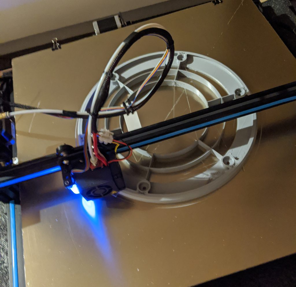
The PEI sheet I got seeing as my official Prusa Mk3S has one, and it is very useful. Just needs a clean after every print with IPA and the next print will stick with no issues. Tho it does need to be heated to work properly I’ve found
BLTouch

The BLTouch probe allows for automatic bed levelling. It doesn’t actually level the bed, but it probes a number of spots and the firmware then compensates as you are printing. The bed still needs to be reasonably level, but it does mean you don’t have to level after every single print.
Motherboard
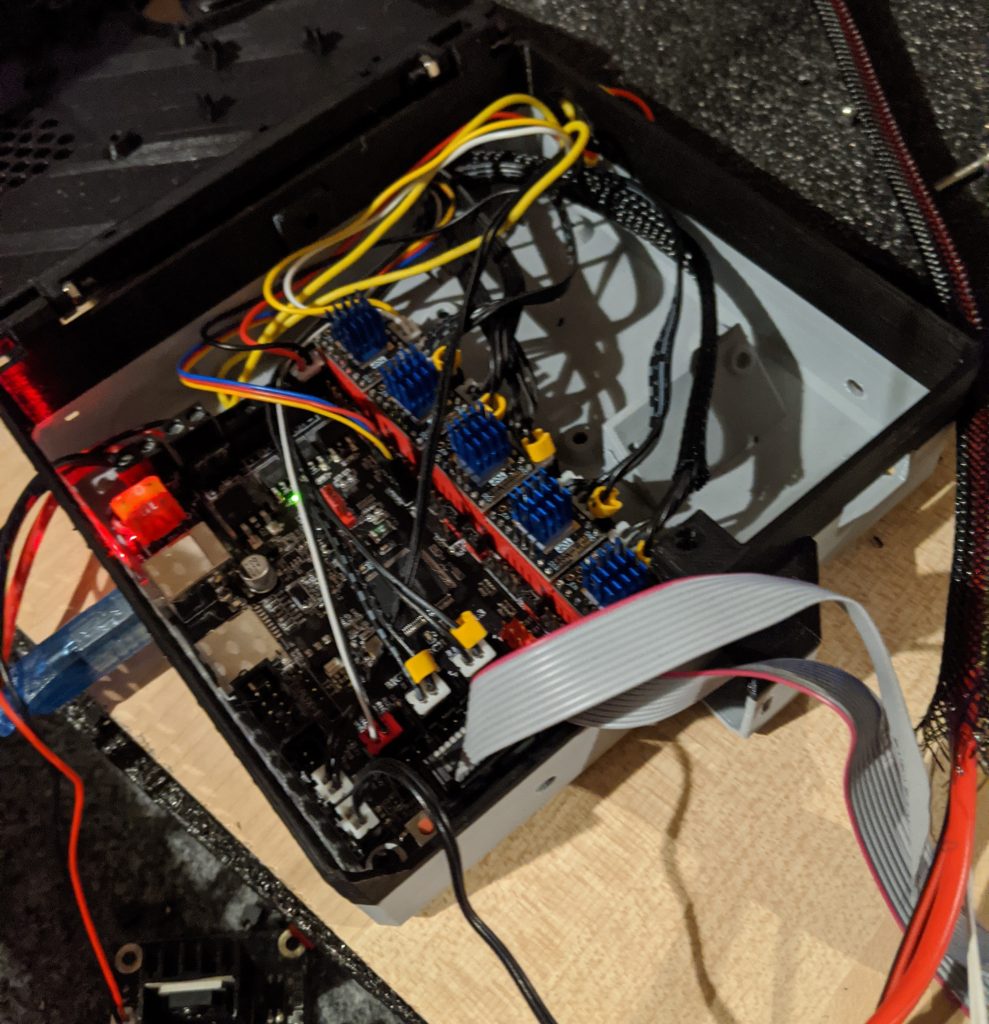
Now this last one. Replacing the motherboard is a bit of an understatement. I basically threw away all the electronics that came with the printer and put new ones in. From the power supply, to the motherboard, to the stepper drivers. The drivers you use can have a lot of effect on the noise of the steppers, so I wanted to go with Trinamic based ones as they can run the steppers really quietly. To get these to work, I got a BigTreeTech SKR 1.3 motherboard, and five drivers. For power I got a 12V 30A power supply, it needs the high current for the heated bed.
The added benefit to this is that it is now a 32bit based machine, with much fewer memory restrictions, and can run Marlin 2.0 firmware. I’ve actually forked the Marlin firmware repo to keep track of the changes I make to the config files:
Results
So far, I am very pleased with how the printer is now running. Bed levelling is a lot easier/non existant, first layer adhesion seems reliable, and we can hardly hear it running in the house, just a dull whine when its doing certain operations.
I’ve also been using PrusaSlicer, rather than the more usual Cura, so I’ve had to do my own profile for the printer. It still needs a few tweaks, but the results are good.
Future Work
Its still not perfect. There are a few things I still want to do to make printing more reliable and to speed it up.
- Braces – The top part of the printer can move quite a bit, so I want to brace this. Might also stop some of the resonance.
- Heated bed cable cover – The cable to the heated bed can get caught or frey, causing many issues and possibly a fire. I want to strengthen that up.
- Tweaks to Marlin – The BLTouch is still a bit temperamental so some more tweaks are needed on that front
- Tweaks to print profile – Still a fair bit of stringing, so the retraction needs increasing. Its also very slow on some operations so I need to find the balance between speed and quality.
- Tidy up – Well, its taken a lot of messing to get it working, and the area around the printer is a state, as well as cables coming out everywhere and the MOSFET for the motherboard hanging loose. Everything (including the Raspberry Pi running Octoprint) needs to be tidied up somewhat.
I’m glad I finally got round to doing all this work, I was seriously at the stage where I thought I was going to get rid of it. But whilst its not up to official Prusa standards, its actually not too bad.
]]>A lot of my TV viewing is Youtube based, and I’m always talking to others about some of the channels I watch. Here is a cultivated list of some of my favourites in a few different categories.
Maker channels
This is a list of channels from the maker community, from woodwork to forge work.
- Tested.com – Adam Savage of Mythbusters fame, along with other tech and geek reviews.
- Alec Steele – Brit now moved to Montana, lots of metal work and some fine detail jewelery.
- April Wilkerson – Wood working mainly, including a recent build of a massive shop.
- AvE – Mad canadian, lots of hints and tips, along with tool tests and teardowns. Plenty of swearing and no holds barred.
- Clickspring – Insane amount of detail and precision on this channel, so hypnotic to watch.
- Colin Furze – Modern British mad scientist/inventor. Builds many dangerous contraptions in his workshop.
- I Like To Make Stuff – Just what it says on the tin. Various DIY home projects and other fun builds.
- Jimmy DiResta – The original Youtube maker, insane skills and brilliant builds.
- Kris Harbour – Lots of sustainable building as he constructs an off grid homestead.
- Primitive Technology – Goes out into the bush with nothing but a camera and a pair of shorts. There he builds huts, kilns, fires bricks, generally goes back to nature.
Space
Various channels that give information about space travel.
- Everyday Astronaut – Bought a russian space suit, took some photographs, now a space science informer. Covers all aspects of rocket science and launches.
- Scott Manley – Originally got popular from playing Kerbal Space Program, now does deep dives into rocket theory and reports on space activities.
- TMRO – Weekly space news, interviews, generally keeps you up to date with what is going on in space.
- The Vintage Space – All about the history of space travel and the people who made it a reality.
Science
All sorts of science and technology videos.
- Applied Science – Crosses the line between theory and application, builds various demos of scientific principals.
- Because Science – Where geek culture and science meet. How do super powers work?
- Cody’s Lab – Science in the real world. Recovering gold, real life minecraft, taking a bath in mercury.
- Curious Droid – Takes a look at aerospace technology, from past to present into the future.
- Practical Engineering – Applies scientific principles in the real world, with many civil engineering examples.
- Real Engineering – A wide ranging dive into various technologies and the science behind them.
- Smarter Every Day – One of the biggest science channels on YouTube, covers topics on anything that takes his fancy, just dives in and figures out how things work.
- Standup Maths – Maths problems, number theories, real world applications, all with a comedic style.
- The Science Asylum – A great explainer of complex ideas such as quantum theory, relativity, and other deep physics ideas.
- Veritasium – Covers science, education, and just about anything else he finds interesting.
Electronics
These channels cover restoration, dismantling, and building of electronic projects.
- Big Clive dot com – Strips down various electronics goods, usually cheap chinese imports, to figure out how they work and review them at the same time.
- Curious Marc – R2 Builder and old computer restorer.
- EEVBlog – Mad Aussie with lots of knowledge of electronics, does tutorials and reviews of electronic devices.
- James Bruton – Robot (including R2 and BB8) builder, gives some good overviews of how things work.
Misc
Have to have a misc section, various geeky or fun channels here.
- Corridor Crew – Vlog of the team behind Corridor Digital. Some great tutorials on film making and special effects, along with fun games.
- Corridor – This is where the Corridor Crew release their finished videos.
- Fact Fiend – No nonsense guy talking about various topics, with many tangents throughout.
- Fully Charged – All about electrics cars and other renewable energy solutions and projects. Hosted by Robert Llewellyn.
- Sneaky Zebra – Cosplay videos and a few small features.
- Slow Mo Guys – They film everything they can in super slow motion, usually at some form of bodily peril.
- Tom Scott – Linguistics, quiz shows, amazing places, things you may not know. All whilst wearing a red t-shirt (definitely recommend watching Citation Needed on this channel)
- Today I Found Out – A daily video about random facts.
That should do for now. I tend to find I watch videos from all these channels as soon as a new one is released. Theres plenty of back catalog to be going on with too.
]]>One of the things I’ve been getting into recently is using Software Defined Radios (SDR) with cheap USB digital TV tuners that are available all over ebay, etc. These have been taking the radio community by storm as the chipset in them from RealTek can tune into a really wide band of frequencies. Usually from down around 20MHz, all the way up to nearly 2GHz.

Typical Digital TV stick with the Realtek chipset in
Tracking the skies
One of the fun and cheap projects you can do is track all the aircraft that are flying around you. All commercial and some light aircraft are required to have an ADS-B transponder that sends out a radio signal on 1090MHz that contains their location, speed, etc. These signals can be received with one of these SDR dongles and decoded to display this information on your computer.
There is even a ready made piece of software called dump1090 (and many, many forks of it) that will also display this information on top of a google map.

Current view of the planes around me
Antenna
The first thing you will need is a decent antenna for receiving these signals. The easiest to make is a quarter wave ground plane. In the simplest terms, this means that the main part of the antenna is a quarter of the wave length of the signal. The equation for this is:
f = c / λ
where f is the frequency, c is the speed of light in m/s, and λ is the wavelength. So to get the wavelength of 1090MHz, you rearrange the equation to:
λ = c / f
Putting the correct numbers into this means that a quarter of a wavelength is just 68.8mm. This makes for a pretty small antenna.
The ground plane is just four more wires at 90 degrees to each other, and bent down at a 45 degree angle.
All these wires are then soldered into a standard SO239 panel socket.

A quarter wave ground plane antenna for 1090MHz
There are many sites that will give a much better walk through of how to make one and the details behind it.
Software
Next, we need to look at the software. At this stage, if all you want to do is have a quick look for some fun, all you need is the antenna, usb stick, and the dump1090 software from one of the many forks (If found the dump1090-mutability one to be best). Download or clone this repo, and follow the compile instructions to give it a try. You should then be able to view the results either on screen or via a web browser.
The other option if you are going to go for a more permanent solution is to maybe use the data to improve a commercial sight such as FlightRadar24. This is what I chose to do, so I signed up for an account with them and followed the instructions to build a dedicated Raspberry Pi receiver that will automatically upload any information I receive to their systems, hence improving their reliability. This also gets you a full business account on there worth $500/year!
Enclosure
Lastly, if you’re doing a permanent solution, you need somewhere to put it. To save space and cost, I just used a Raspberry Pi with an decent sealed enclosure box.

Setup without the enclosure
I used some epoxy to glue the antenna on the end of some 20mm conduit that I had, with the cable passing down through it. Then drilled two holes in the box. One that I put a rubber grommet in to pass the power feed through, and the other to put an external antenna connector through.
Lastly, I used epoxy again to fasten some 20mm brackets to the box lid for the antenna to attach to. This was better than screwing, as fewer holes for moisture/bugs to get in through. Then I just mounted the whole thing on the side of my garage and passed a cable for power to it.

The whole unit is attached to the side of the garage
Ideally it would be placed higher, or at least the antenna would be, but that started to make things complicated. As it is, I can still get signals from planes nearly 200 nautical miles away.
Summary
Now I can access the Pi whilst I’m on my network and view all the planes around me. I also have a full business level account with FlightRadar24. Is there much point? Nope, not really apart from helping crowd source data for a company. Why’d I do it? Because I can and its fun!
]]>Most of the things I do at the moment are R2 related, and I’ve moved that out into a separate blog, so thats where a lot of activity is:
So I really need to do a post or two on here about what I’ve been doing recently that isn’t R2 related. Hopefully I will have some astrophotography stuff soon, and also have a couple of decent 3d printers.
I do want to do a post with an overview of my OpenHAB home automation too, as that is getting quite useful.
Oh, and I’ve also been getting into a few ham radio projects again!
Lets see if I actually do get round to writing about them all.
]]>
Red Electrical came and installed everything very quickly and neatly, very impressed with their work and support in deciding what equipment to go with.
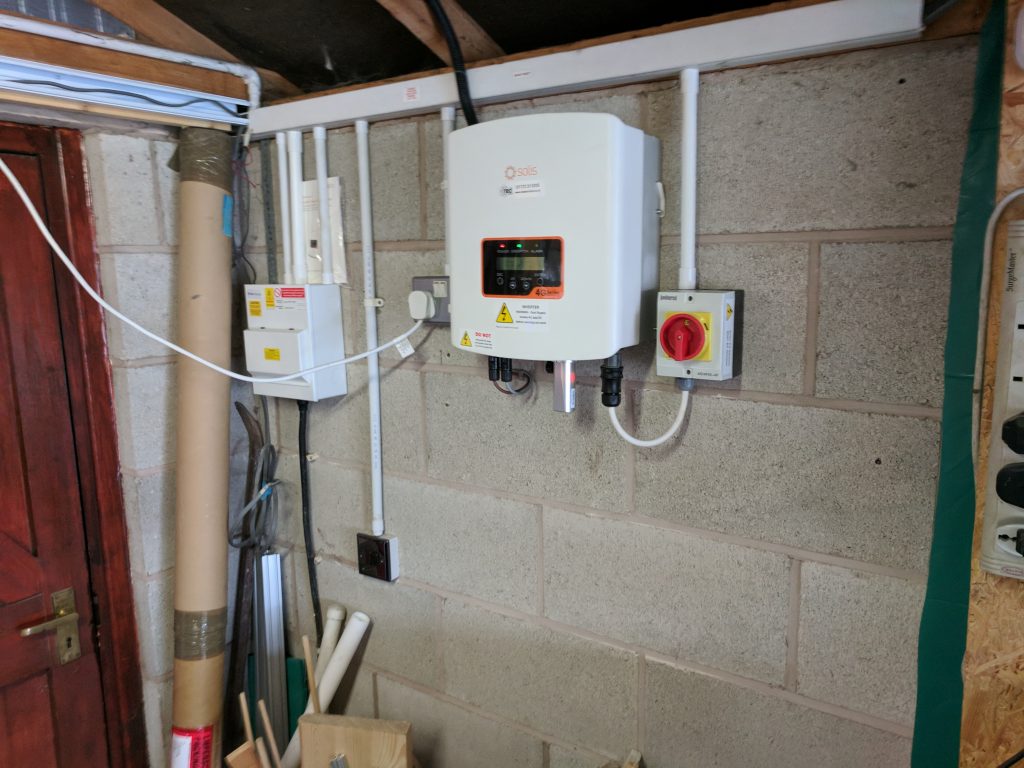
The solar inverter that I went with is a Solis mini 1500 4g by Ginlong. Basically, a single MPPT grid tie inverter that will handle up to 1.5kW. The 4g just means its the fourth generation of their kit. Its a fairly cheap but decent chinese model, and has the option of a wired or wireless monitoring stick. This is where the fun starts!
Monitoring
Now, I like to gather stats about power usage (and just about anything else really), and I rather liked the idea of using data directly from the inverter rather than the more typical way of using clamp meters such as those from Open Energy Monitor, which I have used before. The idea being that data from the inverter will be more accurate than a passive monitoring system.
Of course, it wasn’t going to be that easy. The monitoring stick is designed to push data out to a remote server and you access the data via a portal. The portal isn’t actually that bad, it seems the system is used and rebranded by a number of manufacturers, but this wasn’t good enough for me. I wanted the data fed into my home automation system (OpenHAB), similar to how I’d set up my off grid system.
Thankfully, at least the monitoring stick does support sending to an alternate IP address and port. The problem is, the protocol is not documented anywhere and the manufacturer will not release it. I searched for quite a while under various names and brands and found a few people who had tried to do similar. The newest work in github was from graham0, but was two years old and for a different version of the firmware. However, it did give me a starting point.
Decoding
So, pointing the secondary address of the monitoring stick to my desktop, I started examining the data being sent. There was a choice of a few protocols, but the one that seemed to give the best data was listed as SolarMAN-1.
What I was receiving was a 270 byte string. In HEX this was:
687941b08f4661718f466171810305030507e40100b3930000509ee9590100af
010000XXXXXXXXXXXXXXXXXXXXXXXXXXXXXXXXa7008701060000000000030000
000300620900006209881348000000820000001e000000000000000300000000
00001d0403000000000000000000000010270000009000009000000000000000
000009e2069816
The XXXXXX part are the serial number of the inverter. I figured this out first as it was actually sent in plain ascii. Good start, at least I was getting something.
I worked on the assumption that the rest of the data was encoded similar to the previous protocols as worked out by graham0, I started looking for various 2 and 4 byte blocks. Temperature was quickly found as the first two bytes after the serial number. The rest of the data took a few days to crack. As I logged more of the rawdata to a file, I started pattern matching trends and data to the graphs that the main monitoring portal was producing.
Storing
In the end, I managed to write a program to take in the data and spit out usable stats. My next step will be to pipe this data into my MQTT server. Then OpenHAB can then access it much like my previous solar experiences. I have released the code on github, incase anyone else has a similar setup or wants to extend it. The raw data actually seems to support dual MPPT inverters, and theres a lot of data in there that I haven’t figured out yet.
https://github.com/dpoulson/ginlong-mqtt
So far I’m pretty certain that I’ve got the following stats correct:
- Temperature
- DC Volts (from panels)
- DC Current (from panels)
- AC voltage (grid supply)
- AC Current (how much is fed into the grid)
- AC Frequency (should be around 50Hz)
- kWh produced today
- kWh produced in total
I’ll continue work on it and see what other stats I can pull out, but from this I should be able to calculate most other things.
Is it worth it?
As its only a small solar install, the ROI is going to be quite long compared to the solar on the previous house (only have another year or so and they should be paid off). However, I do think solar is great thing to have. Now if only I could justify a powerwall…
]]>If you want a lightsaber, there are plenty of options. Cheap ones, off the shelf decent ones, upgraded ones, custom ones, and even kits. As I want to learn machining skills I am going down the custom DIY route.
Saber Parts
A saber in its simplest for is:
Sound Board
This is a small board with an accelerometer, LED driver, speaker driver, and a couple of inputs for buttons, with a microcontroller to tie it all together. From research and conversations with my friend Neil (who has his own saber shop, London Sabers) I decided to go with a sound board from a company called Plecter Labs. This is a home run shop that produces a range of sound boards of differing complexity. The boards can be bought in the UK from JQSabers. That is also where I got a lot of the other parts that I needed.

Test wiring of sounds board and other components
LED
These days you have a choice between a single LED cluster in the hilt, or a string of LEDs that run up the inside of the blade. With a string of LEDs you can have a gradual light up of the blade that looks more like the film, but with a single LED cluster in the hilt it makes the blade a lot easier to remove. To keep things simple, my lightsaber will just have a single LED cluster in the hilt. I’ve gone with the Tri Cree XP-E2 which has two blue and one white LEDs on a small circuit board. The white LED allows for something called ‘Flash On Clash’ which, as it sounds, means that when the sound board detects that you’ve hit something, the blade will pulse with an extra white light.

Tri Cree LED
Hilt
This is the part that will be 100% custom for me. There are modular options available, or replica ones if you want something from the film. I’m doing a totally custom design and will all be machined by me on the lathe and mini-mill. It will be a fairly simple design (for this one at least) as my skills on the lathe are not exactly the best yet.

Emitter end of the hilt

Turning the main part of the hilt, adding some cosmetic details
Blade
The blade is just a simple tube with reflective film on the inside to give a smooth lighting. As I want to be able to hit things with my lightsaber, I’ve gone for the thick walled dueling blade.
Progress
So far, I have made the emitter and main part of the hilt, along with doing a test wiring of all the electronics to go inside of it. Quite pleased with how the hilt is coming along, I just need to wait for my new mini-mill to turn up so that I can accurately drill some holes and create areas for the switch to sit. The pommel end of the hilt still needs to be designed, and will house the main speaker. Currently I’m working on some laser cut parts that will hold the internals in place, yet still be easily removed for servicing.

The start of the skeleton for the internals