The post Creating a terrain mask shader first appeared on Baran Kahyaoglu Dev Blog.
The post Creating a terrain mask shader appeared first on Baran Kahyaoglu Dev Blog.
]]>I used a similar effect in my Scifi map project to create a hexagon shaped map and a lot of people asked me about it since then.

As you can guess, this is a common case when you want to put a map on another object, like table or an AR surface. And there are many different ways to do this but in this post, we’ll got for a shader based mask using mask texture and ShaderGraph.
Wait, what is a mask?
According to google; “A texture mask is a grayscale texture used to limit the effects of underlying element”. Or in other words, it’s a texture which dictates where underlying thing will be visible or not. Details of it depends on the implementation I guess but they are all more or less same, be it photoshop mask, 3d shader, UI mask etc etc.

In our case, base “effect” will be a mesh with satellite imagery from Mapbox Unity SDK, mask will be a black and white hexagon jpg and “+” part will be a shader where we tell GPU to draw satellite imagery pixels or not.
Let’s get started!
First two elements, base map and mask should be fairly easy. For this post we can use ZoomableMap demo scene inside Mapbox Unity SDK. It’s a top down map we can pan and zoom so it’s exactly what we need.
For the mask, we will use a very basic hexagon image as seen above. You can find the image here.
But for sure, shader is where all the magic will be. And now we’ll dive into that. I’ll go over the basics fast.
First of all, we decided to use URP and ShaderGraph for this already so let’s be sure those two packages are loaded and project settings are set to use URP properly.
Then let’s create a new shader asset by choosing Create > Shader > PBR Graph from the context menu in project window. And a new material to use that shader. Shader is all empty at the moment but doesn’t matter, we’ll get to that in a minute. Finally, select the Map object in the scene, find the Tile Material field under Abstract Map script, General > Other settings and set your new material there. As the name suggests, this will tell Mapbox Unity SDK to use our new material for terrain meshes.

And if you run the scene now, you should get a white/gray view. That’s expected though as our shader is all empty and it’s just rendering the default color on the mesh.
Let there be colors!
So let’s start with something simple. Let’s create a new Texture field; you can name it anything you want but this is very important; the Reference has to be _BaseMap. Mapbox Unity SDK will be using this name to pass textures to GPU (see Using Mapbox Unity SDK with URP post for details) so if it doesn’t match in code and shader, it won’t work.
Then sample that texture and use it for Albedo channel. I also decreased Smoothness to zero as I just hate that (so just a visual preference).

Color is working now so let’s start with trying the same for alpha.
Create a new Texture field; Reference isn’t that critical for this yet but we’llneed to remember it later. Sample that and use it for Alpha as seen in image below. Our material Surface is set to Opaque by default, let’s change that to Transparent.
Finally, find the material in your project and set the Mask texture to the black and white hexagon image.

Hmm, we have multiple hexagons on our map now. But why?
When we sample mask texture like that, and I mean using default UV values for sample node by “that”, we’re actually doing a sampling in UV space. Remember maps contains bunch of square tiles and each tile has a separate mesh, texture and of course UV space going from (0,0) to (1,1).

On the right is what happens when we apply mask using those coordinates.
We just want one hexagon in a one specific place though, one specific place in world space. So we should somehow map current pixel’s position (relative to mask position) to UV coordinate. Or maybe if we think vice versa, there’ll be a UV space/square (0-1) where we want to place the mask and we need to convert current pixel’s position into that space.

Only shown 6 in the image but of course shader will work for all pixels on terrain mesh.
Reds will be invisible, blues will be visible,
It’s actually not too difficult; first we subtract mask center position from pixel world space position to find the relative position (while lines in image above).
Then we divide that vector by the mask scale, because that rectangle can be any size, right? If it was big enough, it would have contained those red points as well. This will give us a UV space coordinate.
Finally, we’ll rotate this UV vector as your table/environment/surface might not always align with your mask texture. Imagine having a rectangular mask for a rectangular table but it’s rotated in scene.

I posted the whole calculation above but I’ll go through it one by one as well. After all this time using graph editors, I’m still not sure if I love them or not. But I must say, they feel extremely readable (up until some certain point). Easy to get the flow/idea in general.

First part is the positioning. We subtract mask position from pixel position and divide it by the mask scale. Any value inside mask area should be in [-0.5, 0.5] range now.

We convert this position to vector2 and drop Y axis. We’re working in Z plane so Y axis is useless in this case.
Then we remap from [-0.5,0.5] to [0,1] to move it into UV range. Using remap here is a little overkill and this can be optimized but I preferred to do it this way for simplicity.

We rotate it around [0.5, 0.5] because that’s the center of the UV space & mask texture.
Also converting from ccw to cw and degree to radian before that.

And finally we’re saturating (clamp(0,1)) the value. This will enable/disable texture repeating. But it’ll only work if texture asset is set to Repeat mode as well. Otherwise it won’t repeat no matter what this option is.
Now it should technically work but there’s one more small problem. We set our parameters mask position, mask scale etc. in material settings but when we run the project Mapbox SDK clones that material and creates instances of it for each tile because they all have to have different color maps (satellite imagery). Now they all have different materials and if you ever want to tweak some numbers and style it in runtime, you will have to select them all one by one and change the values separately.

So it should all work now and this is totally optional, but I really would like a script where I can tweak all numbers.
Global Shader Variables
We’ll use global shader variables for this. They are static global variables of the shader which you can set from anywhere and they are shared between all instances of the entity. So that’s exactly what we want for fields like mask position, scale etc.

First thing we need to do is to disable inspector support for these parameters. Inspector overrides the values set by code so if they are exposed in the inspector, our code won’t work at all.
You can find this on shader graph blackboard. For every parameters, there should be an Exposed checkbox. If you uncheck that, that parameter will not be on the inspector.
Then we need a C# script to get&set values;
public class ShaderController : MonoBehaviour
    {
        public Texture2D MaskTexture;
        public float MaskScale;
        public float MaskRotation;
        public bool RepeatMask;

        private void Update()
        {
            SetValues();
        }

        private void OnValidate()
        {
            SetValues();
        }

        public void SetValues()
        {
            Shader.SetGlobalTexture("_MaskTexture", MaskTexture);
            Shader.SetGlobalFloat("_MaskScale", MaskScale);
            Shader.SetGlobalFloat("_MaskRotation", MaskRotation);
            Shader.SetGlobalVector("_ReferencePosition", transform.position);
            Shader.SetGlobalInt("_RepeatMask", RepeatMask ? 1 : 0);
        }

        private void OnDrawGizmos()
        {
            var v1 = transform.position + Quaternion.Euler(0, MaskRotation, 0) * new Vector3(- MaskScale/2, 0,  - MaskScale/2);
            var v2 = transform.position + Quaternion.Euler(0, MaskRotation, 0) * new Vector3(- MaskScale/2, 0,  + MaskScale/2);
            var v3 = transform.position + Quaternion.Euler(0, MaskRotation, 0) * new Vector3(+ MaskScale/2, 0,  + MaskScale/2);
            var v4 = transform.position + Quaternion.Euler(0, MaskRotation, 0) * new Vector3(+ MaskScale/2, 0,  - MaskScale/2);

            Gizmos.DrawLine(v1, v2);
            Gizmos.DrawLine(v2, v3);
            Gizmos.DrawLine(v3, v4);
            Gizmos.DrawLine(v4, v1);
        }
    }
It should be straight-forward. OnValidate would have been enough in most cases but this scripts uses objects’ own position for mask position and OnValidate doesn’t fire on position changes so I added Update call as well.
As I said before, this is totally optional but if you like to play around with values as much as I do, you might need it.
I think that’s it for our mask shader! That’s pretty much what I used in all my projects, including the scifi map one I mentioned at the beginning.
Please don’t hesitate to ping me, here or on Twitter (@brnkhy) for any questions.
Posting one final full view of that graph below;

I’m not sure what will be the next post, might be something like terrain elevation shader I guess.
See you next time!
The post Creating a terrain mask shader first appeared on Baran Kahyaoglu Dev Blog.
The post Creating a terrain mask shader appeared first on Baran Kahyaoglu Dev Blog.
]]>The post Mapbox Unity SDK with URP first appeared on Baran Kahyaoglu Dev Blog.
The post Mapbox Unity SDK with URP appeared first on Baran Kahyaoglu Dev Blog.
]]>What’s the problem?
As you might already know, Unity introduced scriptable render pipelines a while ago, with two default sets, Universal Render Pipeline (used to be called Light Weight Render Pipeline) for performance/mobile apps and High Definition Render Pipeline for next-gen(ish) graphics.
Unfortunately, these new scriptable pipelines are not compatible with good old standard pipeline or its assets. Old materials and shaders simply doesn’t work with the new systems. Also some new unity tools, like Shader Graph, doesn’t even support old standard renderer at all and only work with URP or HDRP.
This is a big problem these days as thousands of assets created in standard pipeline are not working on new systems and require some updates or workaround.

It’s the same issue with Mapbox Unity SDK; it was created using Unity’s standard render pipeline and if you import the package in an URP project now, you’ll see all materials/shaders will be broken. And we’ll look into fixing it for URP today!
Fixing the materials
So let’s say you created a new URP project and imported Mapbox Unity SDK. You entered your api key in Mapbox setup window and want to check out some examples. You ran ZoomableMap demo scene aaaand;

If you switch to scene view and check it out, you’ll actually see a mesh is created, it even has the elevation but…. where are the textures?
Pink is the default color in Unity in case shader somehow malfunctions or simply doesn’t work, so it pretty much says; “there is a problem in the shader”.
And if you check Mapbox Unity SDK materials as well, you’ll see something looks really wrong ;

Luckily, URP comes with an easy auto-fix for this; Upgrade Project Materials to UniversalRP Materials button under Edit>Render Pipeline>Universal Render Pipeline menu.

This should update all materials to use URP supported shaders. Now all materials inside Mapbox folders should look fine, not pink at all.
And if you check the demo again, now you should see a grid texture layed upon the terrain mesh. No satellite imagery though so there’s still something slightly off.

Fixing the color map
If you select a tile object from the scene object hierarchy and check its material, you’ll notice that Base Map field is still set to that black and white grid texture. Everything should be loaded by now, satellite imagery, elevation, everything. And actually if you check the UnityTile on the very same object, you can see the satellite image in RasterData field. So things are downloaded, processed but somehow they are not in the material.
The reason for this is how we normally set the material texture. Back in the standard renderer days, we generally used this line to set material textures;
MeshRenderer.sharedMaterial.mainTexture = _rasterData;
and that’s actually just a wrapper for the real thing, real method;
MeshRenderer.sharedMaterial.SetTexture("_MainTex", _rasterData);
But that “real” method is a little uglier and has a magic string in it, right? So most developers tended to use the first option as it often felt simpler. But that’s the problem. That shortened call sets “_MainTex” as you can see in the second call and “_MainTex” was the name of the color map in standard renderer default shaders. But it’s not anymore, not in the URP. (sad face).
Default URP shader uses name “_BaseMap” for color map.
Why? I have no idea really. But if we fix that, we’ll start seeing some colors!
Now if you check UnityTile.cs file, line 305 (under SetRasterData method), you’ll find the line we have to fix.

And we replace that with the following line;

If you run the ZoomableMap scene now, it should be working as expected;

About the fix
Even though it’s a relatively easy fix, it’s hard to push that into the SDK itself mainly because there are three common rendering pipelines with different shaders (and color map names) now. And as far as I know there isn’t a good way to detect which rendering pipeline is being used. If we fix it this way in SDK, all standard renderer and HDRP users will have the problem and vice versa. So we might have to wait at least until URP is the default renderer and that’s happening starting from Unity v2020 I believe.
Also I must add, this is only for the terrain material/imagery. You might run into similar issues on vector layer as well, depending on how to style it of course. But the underlying problem is same.
TLDR;
- Change materials to use URP shaders
- Change
UnityTile.csto set textures by URP shader field names, instead of usingMaterial.mainTexture.
Final Notes

One final small note; if you ever need to find out, ‘what that field is called”; you can switch to debugmode in the inspector and check texture fields of your materials.
You will probably need to do this with HDRP as well for example because if I remember correct, HDRP is using a totally different name as well.
But other than that, debug mode is pretty helpful for a lot of other things anyway. I just didn’t want to mention it before to keep main section a little simpler.
I hope you like it! Please let me know if you have any questions. Also feel free to ping me on twitter! I share almost all my work there; @brnkhy
Ah and now that we have it working on URP, I’m thinking of something fancier, maybe like a mask shader for the next post!
See you next time!
The post Mapbox Unity SDK with URP first appeared on Baran Kahyaoglu Dev Blog.
The post Mapbox Unity SDK with URP appeared first on Baran Kahyaoglu Dev Blog.
]]>The post Cloud visualization in Unity3D first appeared on Baran Kahyaoglu Dev Blog.
The post Cloud visualization in Unity3D appeared first on Baran Kahyaoglu Dev Blog.
]]>Live cloud forecast from @AerisWeather,
— Baran Kahyaoglu (@brnkhy) November 5, 2019
elevation and satellite imagery from @Mapbox,
visualized in @unity3d.#gamedev #madewithunity #indiedev #map #vfx #unity3d #datavisualization pic.twitter.com/nqHsGRBrZl
I got lots of questions about it since then so I thought it might be a good opportunity to break my blog post laziness!
In this post I’ll talk about converting 2d black and white cloud forecast textures provided by AerisWeather into somewhat realistic 3d particle based clouds in Unity. You can do this a few different ways really but I think this is the easiest, fastest (development time wise) and most straightforward one. On the negative side though, it’s a wasteful on particles (until/if I can find a way to improve that part).
We’ll use Unity’s VFX graph for this! VFX Graph makes it extremely easy to work with particles so we’ll be able to focus on (1) creating map url using AerisWeather Map Url Builder, (2) downloading and passing cloud data into VFX graph and (3) how to visualize/style particles.
Creating the cloud map in AerisWeather Map Url Builder
First of all, let’s create our cloud map. AerisWeather website has an amazing `Map Url Builder` tool to help you generate urls fast and very easily.
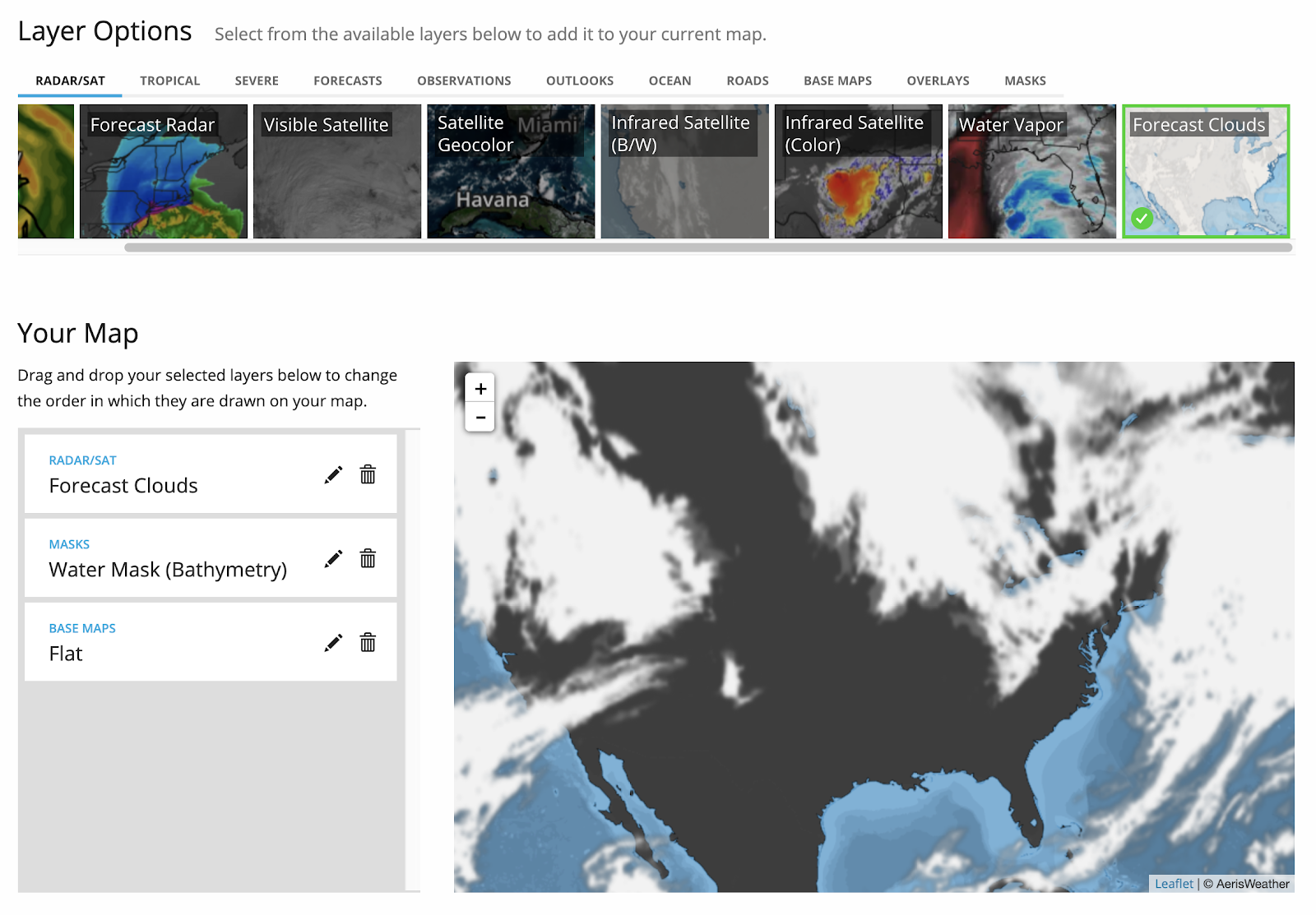
Map Url Builder is pretty easy to use. You add data by clicking buttons on the top menu and they appear in the layers menu on the left. For a readable weather forecast map, you can try flat base map, water mask and forecast clouds for example. This’ll let you see and identify locations and their cloud forecast. But for our project, we won’t need base map or water mask. So disabling them we’ll have our transparent background, cloud only texture and pretty url at the bottom of the page to use inside Unity.
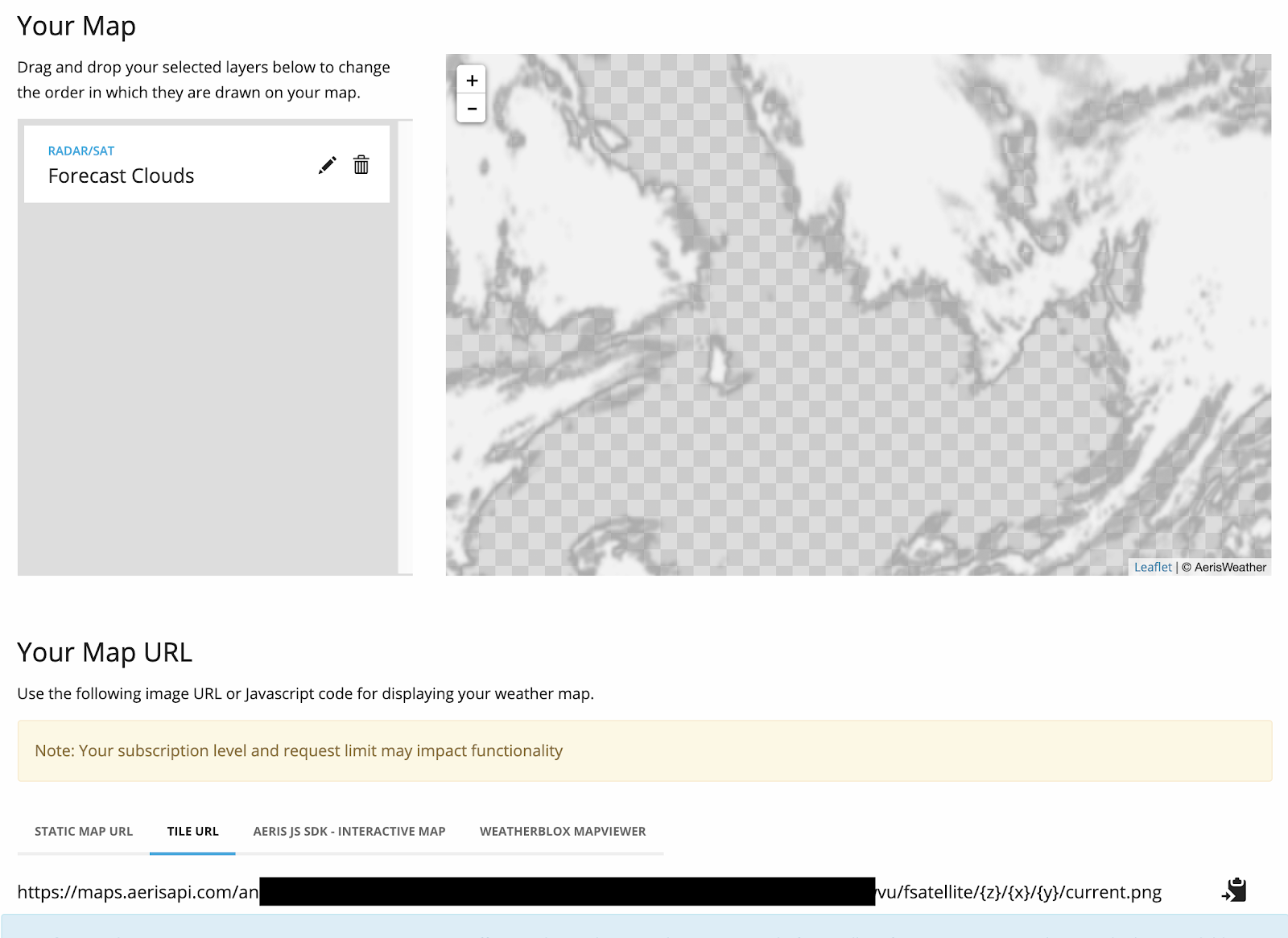
I specifically choose Tile URL option there as I’m planning to decide which tiles to call inside unity, which will help me extend the project if necessary later on (i.e. rendering a whole region with multiple tiles instead of one static tile).
Downloading and passing cloud data into VFX graph
Now that we have our map, we can download it on Unity side and see what it looks like there. I used UnityWebRequestTexture to pull the texture, it’s async and returns a Texture2D just as I need. It doesn’t provide too much flexibility or anything but gets the basic job done very well.
So first I have bunch of fields for map url, my private api key, the vfx graph instance I will use and a Texture2D field to keep my cloud data.
[NonSerialized] private string _url = "https://maps.aerisapi.com/{3}/fsatellite/{0}/{1}/{2}/current.png";
[SerializeField] private string ApiKey;
[SerializeField] private VisualEffect _visualEffect;
[SerializeField] private Texture2D _texture;
If you’re not familiar with string formatting in C#, sections like {0} inside the map url means that I’ll use this string as a template but add additional data in place of {0} . You’ll how it works in a second. ApiKey is a serialized private field to make it easier to add and change through unity editor and scene. Same for VisualEffect actually. I’m planning to have one in my scene and use that one directly instead of instantiating in code. Just for ease of use really. And finally Texture2D is serialized so I’ll be able to see what it looks like in the inspector.
private IEnumerator DownloadImage(int z, int x, int y) { var fullUrl = string.Format(_url, z, x, y, ApiKey); using (UnityWebRequest uwr = UnityWebRequestTexture.GetTexture(fullUrl)) { yield return uwr.SendWebRequest(); if (uwr.isNetworkError || uwr.isHttpError) { Debug.Log(uwr.error); } else { _texture = DownloadHandlerTexture.GetContent(uwr); _visualEffect.SetTexture("CloudTexture", _texture); } } } |
This DownloadImage method takes three parameters necessary to identify a map tile. Then it uses url template with these parameters and api key, creating a real url to use. Using block is pretty much how use use UnityWebRequestTexture. We make the call, start waiting for response. Then if it return an error we log it; if not, we create a texture and use SetTexture method to pass it into the visual effect object.
Finally I created a basic scene with just a few objects and scripts which looks like this;

There’s only one custom object named Clouds in the scene and it hosts both OverlayImagery script containing the functions above and Visual Effect script containing the vfx we’ll create in next section.
How to visualize cloud particles
I’ll try to explain everything but first of all, this is how the whole thing looks like;

Idea is rather simple really. I’m using a regular flipbook based cloud particle but since VFX graph doesn’t support spawning by a map (at least as far as I know), I’m doing a little trick by spawning particles everywhere but setting their scale and opacity by the alpha value of the given texture. Remember how the texture we created in AerisWeather Map Url Builder had transparent background? So if there’s no cloud, a value will be zero, particle scale and alpha will also be set zero, hence no clouds in that region.Of course this is a little wasteful as we’ll end up with lots of unused particles in empty spaces but it will work for now.
Now let’s have a closer look at stuff;

We’ll use two parameters;
(1) Size to determine how big the tile will be in Unity space. Texture we’ll get from AerisWeather will be 256×256 but most of the time you’ll want your tile to a different size in your application. So size will scale everything down/up to that value.
(2) CloudTexture to determine where the clouds will be. This is the cloud texture we get from AerisWeather and we set at the end of the code block above.

We create 1000 particles and randomly place them in a size x size AABox. We set their scale and alpha to zero to make them totally invisible initially. This random placement might feel little unreliable but since we have a big number of particles, it’s generally enough to fill up the tile and add some noise/irregularity to make it feel more organic. Of course you might need to increase particle count as the tile size increases though.

This is how we create a flipbook cloud. Flipbook player component will update the sprite and Face Camera Plane, as the name suggest, will turn it towards the camera. You can play with the Crop Factor if it doesn’t look smooth on edges.
If I remember correct, I used image sequences from this old Unity blog post; https://blogs.unity3d.com/2016/11/28/free-vfx-image-sequences-flipbooks/
You can try it with other image sequences as well but don’t forget to change Flip Book Size if necessary.

This is the section where we read alpha value of corresponding pixel for each particle. We take the position of randomly created and placed particle, scale that position down to [0-1] range as we’ll use it as UV coordinates. Then query CloudTexture in that position and take the alpha value of the color.

And finally this is where we do the final tweaks on particle scale and opacity. We use original alpha value from cloud texture on a curve to have more flexibility on style and look. For example if you check the curve a little, it returns 0 for any value below 0.15 which helps hiding small clouds and have a little more contrast on the cloud edges. You can play with all this to match you app/game style and needs of course, this is the fun part!
And that’s it! I hope you like it and/or at least find it useful somehow. I’ll probably continue this with Mapbox Unity SDK integration post soon.
Cheers!
The post Cloud visualization in Unity3D first appeared on Baran Kahyaoglu Dev Blog.
The post Cloud visualization in Unity3D appeared first on Baran Kahyaoglu Dev Blog.
]]>The post Tiled Maps using Mapbox Unity SDK first appeared on Baran Kahyaoglu Dev Blog.
The post Tiled Maps using Mapbox Unity SDK appeared first on Baran Kahyaoglu Dev Blog.
]]>I kept saying I’ll blog this for so long but finally, here it is; creating tiled maps using Mapbox and Unity3d! Well at least I’m starting, we’ll see how it’ll turn out.
First of all, a little bit of background;
It actually all started with some 2d map experiments I did like 8 months ago. I was trying to create a 2d fantasy theme map and after checking some examples online, I decided to go with a hexagon tile based map. I always loved hexagons to begin with but on the technical side, I thought it would also help to place visuals/models to represent map entities.
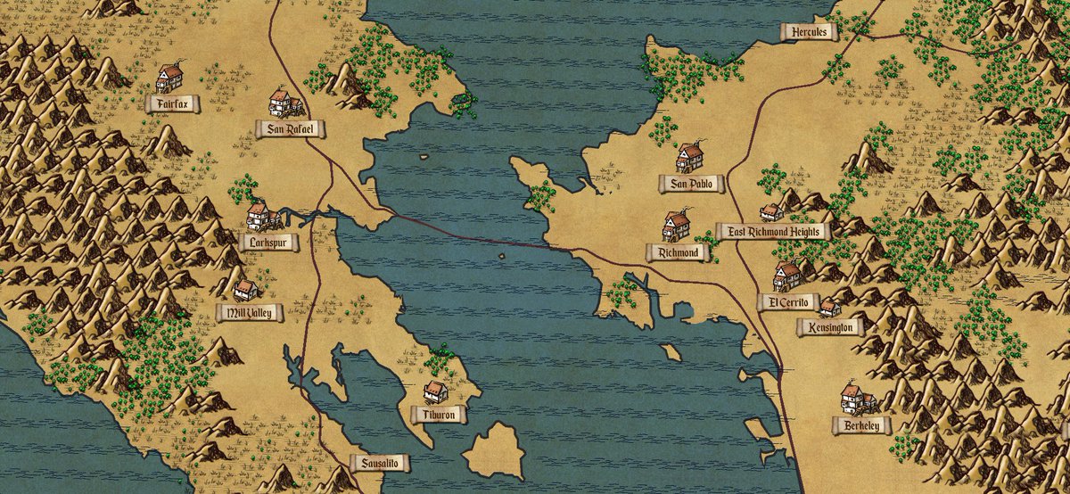
If you check the forests or water, you probably can notice the hexagon grid. I still love the style but it was pretty hard to find/create art assets for this so it ended up kinda… ugly? I didn’t get too much attention either as it was rather unpolished, more like a proof of concept at the time. I’m pretty sure it could have been soo much better with a 2d artist.
Then one night, while searching for art assets, I stumbled upon a beautiful package in Unity asset store with beautiful toonish hexagon tiles. With a little change in the code, I created this;
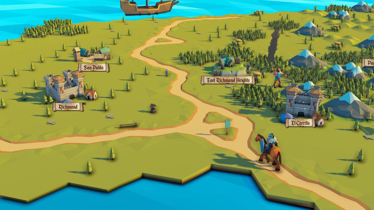
This one got quite popular, probably mostly due to beautiful art assets. It’s just a lot more fun and interesting to look. Also this time I spent a little more time to polish it with some animations and units moving around.
But shortly, the idea was to turn a regular vector map into a tiled map;
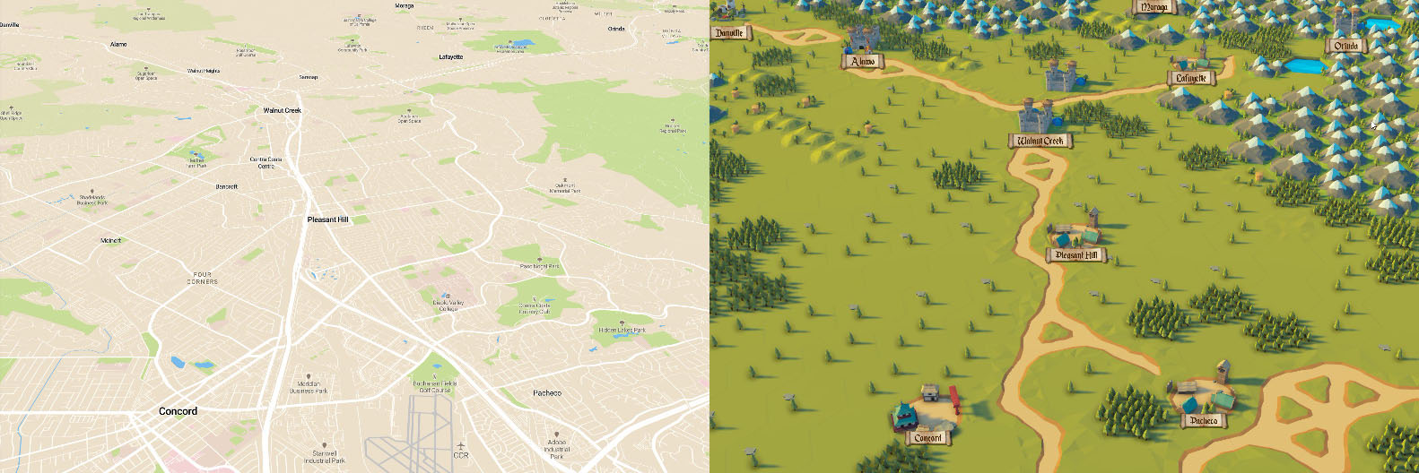
It’s actually quite a fun real map and I believe it can be useful for a lot of different type of applications; PokemonGo type of mobile games, Civilization type of desktop games or mobile location based messaging apps.
About this post
Now I want to clearly note that I won’t share any code in this post. This was an experimental project for me and my goal was to see what I can do (and collect some internet points) so my implementation was rather rough, buggy, pretty unoptimized. I will, however, try to explain who process so you can do better!
So how do we start?
I started with exploring the vector data and try to see what we can get out of that one first. All vector layers aren’t available on all levels and their detail level varies quite a bit as well so I had to try a few settings until I created this;
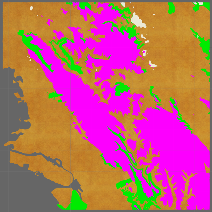
This strange looking map will be our starting point. Yellow textured part here is “land”, pink is “mountain”, green is “forests” and white is “grass”.
Actually I had to do some tricky stuff to achieve some of these layers. Mapbox vector data doesn’t have “land” for example, or mountains. To be able to create them, I used “contour” layer (see https://www.mapbox.com/vector-tiles/mapbox-terrain/#contour). In case you’re not familiar with contour lines, this is what they look like;
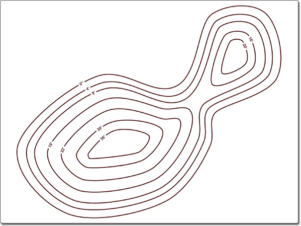
Now our goal is to find the polygons/heights we want to define as “land” and “mountain”.
Land is easy, elevation=0 should be land, right?
Mountains though a little bit trickier as contour layer uses different intervals on each zoom level so this value kinda depends on it. For example, “elevation 200” would work for all levels above 10 but it won’t work for zoom level 9 as it uses 500 meter intervals and there won’t be “elevation 200” in that level.
I created my demos using zoom level 10 as it felt the best for big areas, and at z10 I used;
- Contour layer elevation=0 for land
- Landcover layer class=grass for grass
- Landuse layer for forests (I didn’t filter by type/class as landuses are mostly national parks at this level)
- Contour layer elevation=200 for mountains
I also ordered them bottom to top so the latter will be on top of former and it all results in that top down shot above.
So now we have the polygons, what’s next?
Rasterization
Wikipedia defines rasterization as; “the task of taking an image described in a vector graphics format (shapes) and converting it into a raster image (pixels or dots).”
Exactly what we’re looking for!
We have the polygons so now what we have to do is (basically) to rasterize these polygons, which will yield us a set of tiles, and visualize those tiles.
Now it gets a little more implementation specific, I’ll try to describe how I did it but I’m pretty sure there might be better approaches as well.
We already know these polygons generally overlap and then we’ll also want to play with neighbourhood relations in between tiles (i.e. roads or special models for city by water/mountain) so instead of creating tiles one by one (as they are created), I decided to pass them all to a controller class first. And only after it’s all finished, I process them and create visuals in one final loop.
Also, I tried not to change SDK code at all and built this on top of it as a separate layer. Having whole SDK and a new layer on top of it means an unoptimized structure but it’s easy and faster to develop.
Mapbox Unity SDK Components
If you’re familiar with the Mapbox Unity SDK, you know it’s rather easy to create polygons from features. Most demos and example do much more than creating the polygon so it might be easy to overlook.
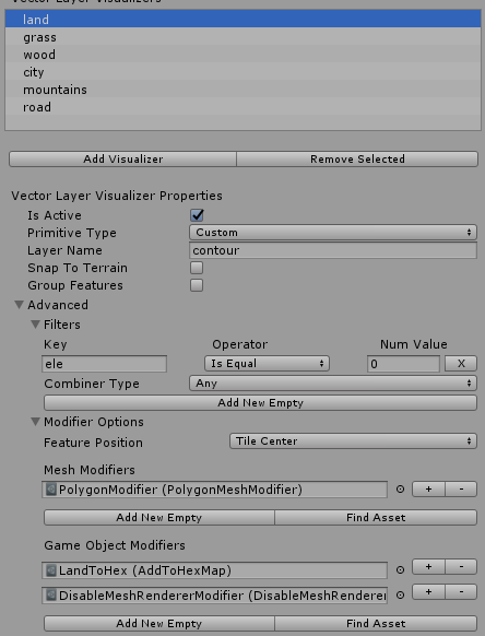
This is my “land” layer in the SDK side for example. It uses custom styling and “contour” layer name. Then filters by the “ele” property and takes the ones with value 0 (coastline).
PolygonMeshModifier creates the polygon, AddToHexMap modifier adds it to our other layer, tiled map controller. And finally DisableMeshRenderer hides the original polygon.
And actually, depending on your rasterization technique, you might not need the PolygonMeshModifier at all. I used it because if I remember correct, I was using triangles for rasterization and needed the triangulation inside PolygonMeshModifier.
So shortly, whole idea here is to pass features to the TiledMapController and do everything tiled there. We’re using SDK only to parse, categorize, filter etc the features.
AddToHexMap here is a very simple custom game object modifier and all it does is passing a few values to the tiled map controller, including feature data, tile, layer (land, forest etc) and type of data (point/line/polygon). My implementation didn’t include dynamic tile loading so it didn’t destroy objects. When you need that though, AddToHexMap can send signal to controller for the destruction of features and tiles as well.
Visualization
This way tiled map controller will get all features, layers and types. Then I rasterized polygons to find the list of tiles covering given polygon and kept them in a Dictionary<Vector2, TileFeature> where the first parameter is the tile position and second one is an enum corresponding to the layer name (land/forest/mountain etc). There’s a few advantages of this; first of all, tile coordinates are rather easy to calculate and Dictionary provides O(1) read complexity in that very common case. Second, it helps to layer things like using forest over land. Vector layer execution order should also be enough but this is nice to have. Third, again it helps with some basic tile type relations; i.e. if current value is forest and you get mountain, you can switch to a custom type like mountain forests.
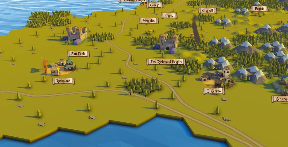
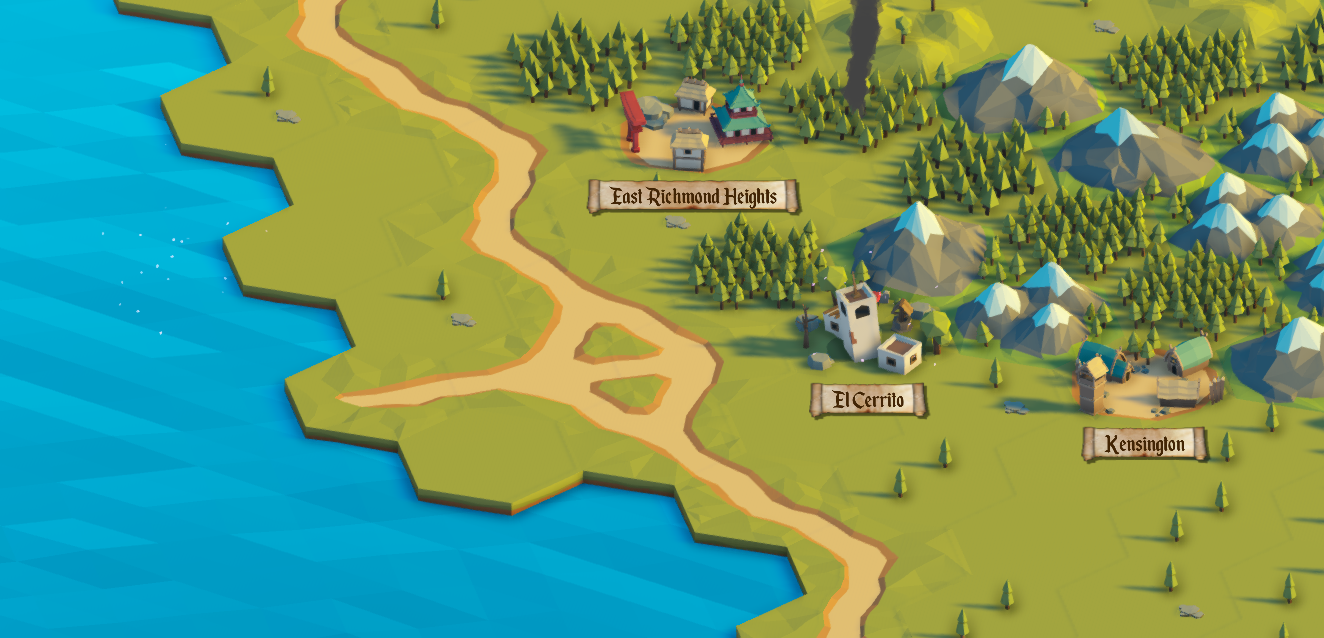
I kept and processed roads separately as they were kinda afterthought in my case. I’m sure you can process them in same pipeline but might require a little more effort.
At this point our dictionary should be full of tiles. Now we’ll wait for the AbstractMap.MapVisualizer.OnMapVisualizerStateChanged event, which means all features are processed and you can start creating your tile visuals.
For visuals, I used POLYGON MINI - Fantasy Pack by Synty Studios (https://assetstore.unity.com/packages/3d/props/exterior/polygon-mini-fantasy-pack-96800). Created bunch of variations for each layer type and saved them in lists. Then went through the tile dictionary and picked a random tile from the list corresponding to tile TileFeature.
Final Words
Looking back, the most difficult part of this project was the rasterization algorithm which I shamelessly avoided in this post. I only had a subpar rasterization implementation but it worked so I didn’t bother to improve it for now. I’m sure there are much better hex/square tile rasterization formulas online though.
I think it covers the main idea behind tiled maps. I really love this project and will definitely get back to it at some point.
Please let me know if you have any questions or if you like it or not!
The post Tiled Maps using Mapbox Unity SDK first appeared on Baran Kahyaoglu Dev Blog.
The post Tiled Maps using Mapbox Unity SDK appeared first on Baran Kahyaoglu Dev Blog.
]]>The post Lines and polygons in Mapbox Unity SDK first appeared on Baran Kahyaoglu Dev Blog.
The post Lines and polygons in Mapbox Unity SDK appeared first on Baran Kahyaoglu Dev Blog.
]]>
We can classify geometry types in Mapbox vector api in three groups; points (pois, labels etc), lines (roads, borders etc) and polygons (buildings, landuse, water etc). We’ll leave points aside for this post. They are quite interesting as well so might come back to that in another post though.
And actually let me just take a small step back and describe how these types are used. So we have this vector data right? It’s all hierarchical so you can visualizer it as xml or json in your head.
Root of the vector data contains a list of layers; like building layer and road layer. They have such names but there’s nothing else indicating what kind of layer it is and how it should be visualized so it’s all abstract. Inside these layers, we have “features”, individual buildings or road segments and these feature actually have lots of meta data with them, most importantly (for this blog post) the “GeometryType” of that feature. So shortly, we have bunch of layers containing features with “GeometryType” property.
You probably noticed how I’m emphasizing “GeometryType” right? That’s mainly because we don’t use this property anywhere at all. Sounds weird huh? Maybe a little, and we probably will use it at some point for certain special cases but one of our main goals with Unity SDK is to make it flexible so there are no restrictions or anything on what to use. So for example, you can render building data as lines to create walls or lakes data as lines to create shore.

Another interesting thing to note here is that, GeometryType is just a property under feature. Other than that, both line and polygon features (even points actually) uses same structure to keep their data; list of vertices. Only difference between two is that polygon vertex list is closed (first and last vertices are same) and line vertex list is open.
Now let me show you the difference data&modifier makes. I’ll use the terraced terrain demo in the latest version of SDK and chamge some properties and stuff there. You can create similar stuff using that as well.

What you see in that image is just one contour line feature, at the corner of a tile. So this tile has that a little elevation at the south west corner. That polygon is created using a mesh factory with “mapbox.mapbox-terrain-v2” source id (you can find its detailes here; Vector Data page), which comes as default in that demo scene. I’m saying that because v2 of that api has contour lines defined as polygons. And then I used PolygonMeshModifier to visualize it as a polygon. Nothing fancy so far. But for example, what happens when you use line mesh modifier on a polygon?

If you can ignore how ugly it looks on sharp edges, you’ll see it creates an outline. It’s kind of useless for contour I guess…. but maybe not. It’s all up to your imagination in the end. But as I mentioned before, you can create borders of a lake or a park with this. And I promise I’ll improve that corners thing soon! 
Now I’ll switch source id to “mapbox.mapbox-terrain-v1”. So this version has contour feature as lines. It doesn’t mean much though, just that first&last vertices in the list are not the same. But let’s have a look at how both modifiers work with that;

This is the v1 data with line mesh modifier. Important thing to note here, since v2 actually filled the whole space adding an extra vertex at the bottom left corner so it looks like a big triangular area. But real contour line is actually just this line, and without a need to fill empty space to create a polygon, we get a nice clean contour line using this.
Finally, what happens when you use polygon mesh modifier on a line;
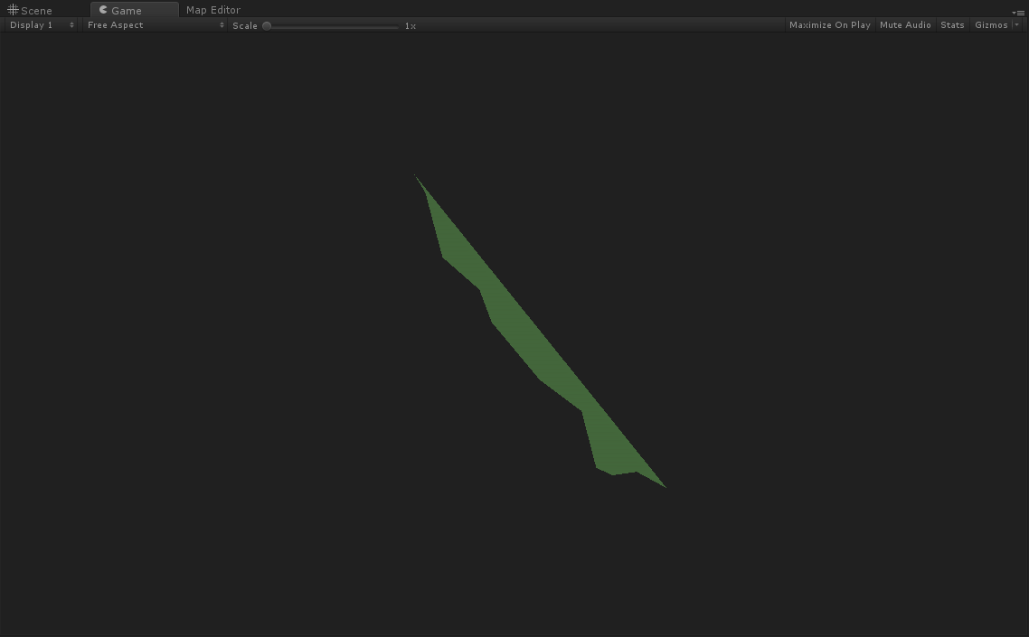
Yep. It’s not surprising I guess but polygon modifier normally created a polygon connecting the first and last vertices, and ended up with this totally wrong output. I think it’s safe to say that this is flat out wrong as I can’t think of a single use case.
To summarize it quickly, we have two geometry types (line and polygon) and two core mesh modifiers (line mesh and polygon mesh) which you can use in bunch of different ways to create different outputs.
Admittedly system doesn’t help you with these either , like saying that it would be better to use polygon on buildings etc. We’ll look into that soon and try to add some guidance&help beyond the demo scenes though.
Finally, I’ll show you the mesh gen structure to create those scifi and terrace styles using the brand new node editor I’m working on these days!

This is the terraced terrain style, actually what you already have in that demo scene. Still wanted to post this so you can see how it actually looks on a graph and understand that demo better. This is using “mapbox.mapbox-terrain-v2”.
And for the scifi style;

It’s almost exactly same really, just have a line mesh modifier instead of a polygon mesh modifier. And “Scifi Mesh Factory” there is using “mapbox.mapbox-terrain-v1” of course. We probably will also have a walkthrough/tutorial for this at Mapbox blog soon as well.
And this is it. Hope you helps you understand what’s going on behind the scenes a little better. Let me know if you have any questions or feedback about this blog post or SDK in general.
Cheers,
Baran
The post Lines and polygons in Mapbox Unity SDK first appeared on Baran Kahyaoglu Dev Blog.
The post Lines and polygons in Mapbox Unity SDK appeared first on Baran Kahyaoglu Dev Blog.
]]>The post New job, new project, new horizons first appeared on Baran Kahyaoglu Dev Blog.
The post New job, new project, new horizons appeared first on Baran Kahyaoglu Dev Blog.
]]>Mapbox is a huge custom map provider and they’ve been one of the top player in the scene for years. They have some awesome terrain (height), vector, satellite imagery APIs and most of their project are open source and hosted on Github! Now they (well it’s “we” now I guess) are going into gaming scene and started this Mapbox SDK for Unity3D project a short while ago. Aaannnd before you ask, yes, this SDK will be open source after the launch as well!
So that’s pretty much the whole story I guess, let’s try this for the rest;
-What will you be doing there?
I’ll mostly do the mesh generation and unity integration, so same as MapzenGO.
-What will happen to MapzenGo?
It really isn’t an easy job building worlds from scratch, there’s millions of thing to do. I can’t do it all for two project at the same time so I’ll switch MapzenGo to maintanence mode. I’ll keep fixing bugs and answering everything as much as I can but I won’t add new features and stuff anymore. It’ll be like an “Introduction to GeoJson mesh generation in Unity3D”. Again Mapbox will be open source anyway so you won’t miss out on anything!
-And blog posts?
I probably won’t have much time for detailed technical posts, at least until the release. I’ll post images, videos or anything though. I’ll keep this blog alive and try to write technical stuff as much as I can. Meanwhile you can follow me on Twitter for updates and mail me for anything. You may already know that I love talking, so don’t hesitate to say hi!
Thanks for everything guy, it has been awesome working on MapzenGo and doing this blog. Please try out the Mapbox SDK Unity beta and tell us what you think. It’s a developer tool afterall, your feedback is extremely important for us.
Cheers,
Baran
The post New job, new project, new horizons first appeared on Baran Kahyaoglu Dev Blog.
The post New job, new project, new horizons appeared first on Baran Kahyaoglu Dev Blog.
]]>The post MapzenGo Part 8 : Places and Pois first appeared on Baran Kahyaoglu Dev Blog.
The post MapzenGo Part 8 : Places and Pois appeared first on Baran Kahyaoglu Dev Blog.
]]>I just realized that I have to blog now and can’t run away from it anymore. It’s soo much harder than coding really. After all these years and so many posts, I still feel horrible at blogging and incredible nervous while writing… But anyway, I have lots of new stuff, two new layers, no wait three even; earth, places and pois, this time! New and better triangulation library, improved settings window, brand new UI visualization and lots of bug fixes. So let’s have a look;
-Let’s start small, well I added the earth layer… just because. It’s just a clone of landuse and water layers really, nothing interesting here. Admittedly I hardly even tested it. I believe it’s coming from Natural Earth api, remember Mapzen is OpenStreetMap + Natural Earth. It has some interesting features like cliff, ridge, valley but well, I’ve always been much more interested in cities so personally didn’t find it that useful.
-No worries, I have something better; places and poi (Point of interest) layers!
Places layers is like a list of populated places; cities, towns, neighbourhoods etc. It’s extremely useful for city/state/country names at low zoom levels and neighborhood names in high zoom levels. It looks great coupled with boundary layer as well.
Poi level is even more interesting, it’s a huge list of…. interesting points… yeah. It has lots of places like Apple Store, H&M, Walgreens categorized under so many different “types”. You can check the Mapzen documentation, it’s quite detailed and explains many new properties very well.
 City and neighbourhood labels
One important thing to note here though, both these layers use the screen space UI and not the 3D world like the others. Why? Well I initially created 3D markers, like pokestops in PokemonGo but they were extremely hard to use (overlapping with each other) and understand. And you probably already know how horrible is the Unity3D TextMesh component is. I also tried using icons on a billboard but sprites looked blurry and low quality as well. Instead I put an empty gameobject in the 3D world (as a marker) and an icon on UI which sticks to that empty gameobject on every update. It looks a lot better this way, easier to read text/icons and interact with them. If you want 3D objects though, you can still use those empty gameobject as well!
 UI elements on pois
-OK what else? Hmm hmm hmm… Ah the UV mappings! I won’t go into too much detail with these as it’s tiny little bit complex and hard to explain but we have UVs now. Roads, landscape and water UV mapping was quite easy with repetitive textures really. Building UV mapping is a little harder and not really complete but if you’re interested, you can read our little discussion about it in this Github issue. You can see roads, park and building UVs in the image below.
 MapzenGo with “First-result-on-google” textures
-By the way, you probably noticed how almost every screenshot has a different style right? It’s all just tweaking settings and materials, I’m not keeping any code from you guys. You can achieve all those in like 5-10 minutes of work (after you have a grasp on the general structure). For example, I got bored a few nights ago and created this PokemonGo style in a few minutes; with roads, buildings and pokemons!
That being said, I’m well aware that it’s also quite hard to switch between styles and this is I’m planning to look into soon as well and you’ll probably be able to drag&drop different styles after that.
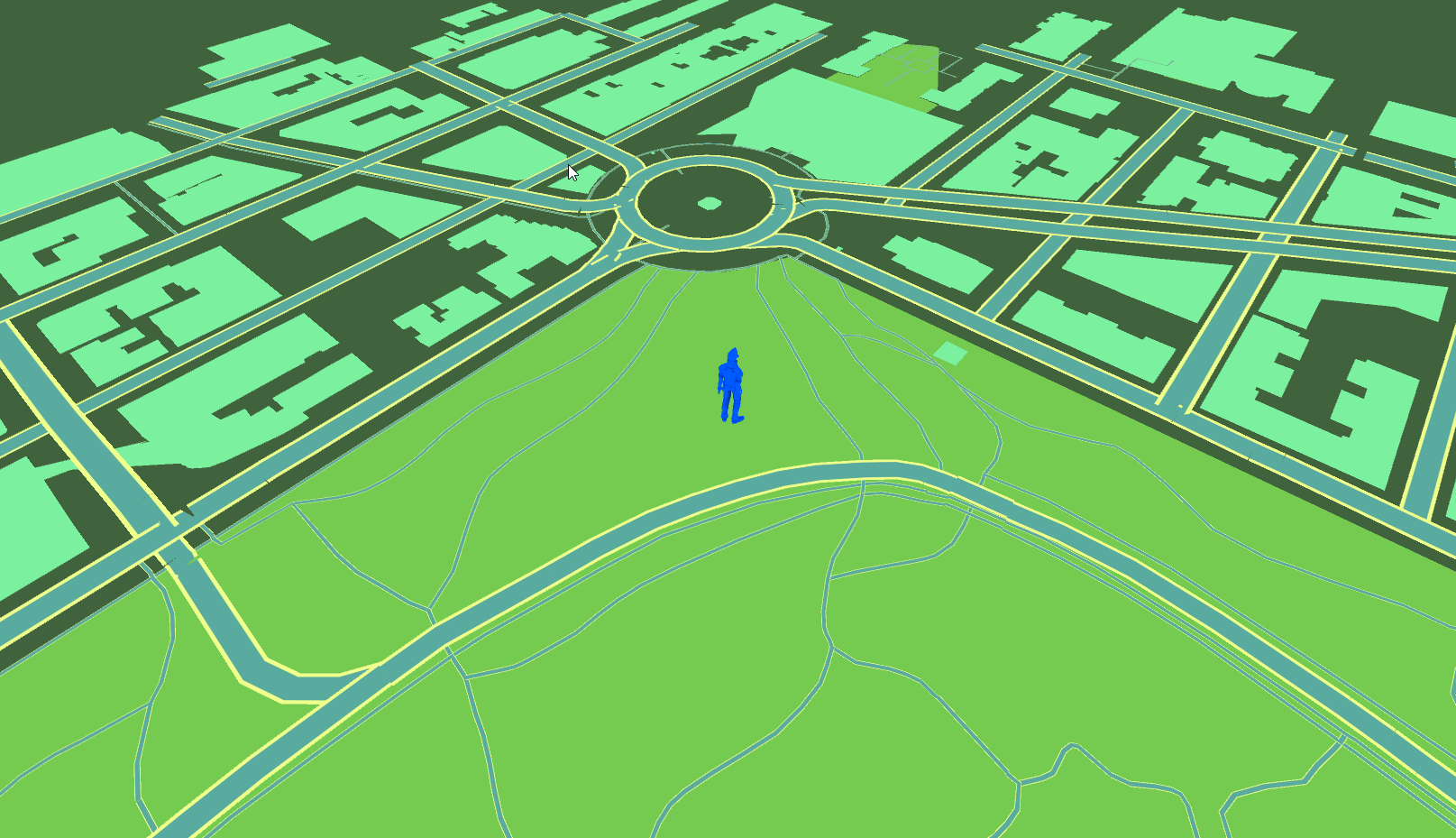

There are probably bunch of other stuff I’m forgetting at the moment but it’s getting late, I’m getting tired so I’ll just cut it here.
 Manhattan after 50 post process image effects
What’s next? Well I want to restructure the folder hierarchy first. Not sure exactly about this one yet but I want to switch to factory/layer focused hierarchy where everything related to a single layer rests under one folder. That way it’ll be easier to plug in/out layers into any project.
Then I want a slightly different factory/settings management system. Roman’s (kind gentlemen who wrote all the settings scripts) gonna kill me , I know but I have…some ideas. Yea that sounds bad… I just want to make it easier to use, plug stuff in/out, tweak, change styles etc etc. Unfortunately I’m horrible at editor scripts so might not be able to do this for a while.
Then maybe some improvements for the UI icons of poi and places layers. Or some road mesh improvements (smoother curves? pavements?) Oh and I’m planning to drop/change the running guy thing as it takes like the 90% of the package size. And he’s not even that handsome.
Anyway so yeah, I’ll keep working on it as much as I can. Please do keep posting me… whatever. I just love hearing from you guys. That’s pretty much what keeps me going.
Cheers,
Baran
MapzenGo Github Page
Twitter
Download MapzenGo Part 8
(v8.1 @5.10.2016, removed unnecessary image effects folder)
(v8.2 @5.10.2016, fixed BasicLoader and DynamicLoader scenes)
(v8.3 @5.10.2016, fixed some default values and settings for Poi factory)
(v8.4 @15.10.2016, Mapzen Api v1 compatibility)
(v8.5 @28.10.2016, fixed a small bug where scriptable object doesn’t run in non-windows platforms)
(v8.6 @18.12.2016, updated UniRx)
[paypal_donation_button]
The post MapzenGo Part 8 : Places and Pois first appeared on Baran Kahyaoglu Dev Blog.
The post MapzenGo Part 8 : Places and Pois appeared first on Baran Kahyaoglu Dev Blog.
]]>The post MapzenGo Part 7 : Plugins first appeared on Baran Kahyaoglu Dev Blog.
The post MapzenGo Part 7 : Plugins appeared first on Baran Kahyaoglu Dev Blog.
]]>Anyway, we have another big update here. Mainly infrastructure stuff but I think you’ll all find them useful.
 Good old Manhattan
-Major thing here is the new plugin system. Well I changed the factories a bit…again but nothing big really. First of all, I introduced a new base class called “Plugin”. It has a simple “Create” function and will be used for both factories and additional… plugins. So plugins are classes which operates on Tiles. Simple as that. Factories take tiles and creates buildings, roads etc. Other plugins, takes tiles and puts map images on them, add custom objects, maybe create forests or something.
So now you can create a class, inherit it from plugin, fill up the create method and put it under the World object in the scene. It’ll work right away.
That being said, I’m not done with refactoring the factories yet, I’ll remove the create from base factory class and leave that part to sub classes as well. That won’t effect the plugin system though, you’ll be able to work on your own plugins unaffected.
-Then I implement as very simple CustomObjectPlugin. People has been asking about how to visualized their own custom locations for weeks now. And yes it wasn’t really straight forward how to convert lat/long to unity3d position but this new plugin should help you with that. It’s just a sample really, nothing fancy going on there and you’ll probably need something much more complex for your needs but this should be enough to get you started.
-Then there is a great editor script, written by Roman (thanks mate!), to search places and use their lat/long right away. Admittedly I haven’t checked the code in detail but it uses Mapzen search api to find places, retrieve their lat/long and pass it to the tile manager. It’s so much easier now to navigate between different places, be it Manhatta, Paris or Istanbul.
 So much easier to test different place now.
-And I also fixed namespaces to match file locations. Should have done this much earlier, no idea how I missed it.
-Oh wait I actually forgot the biggest thing, entity settings and filtering! Well I did talked about this a little in previous posts but extended it a lot since then.
Ok, what is it? Remember, we didn’t have much chance to customize stuff before; hust some hard coded materials which wasn’t enough for anything really. No chance to set road widths, materials by building type etc.
So we have a new settings system to fix that! If you check the factory objects in the scene, you’ll see that there is a new Settings list under it. Using that list, you can customize, let’s say highway roads width or religious buildings material.
Even better, some factories (not all) are using those settings to filter entities, i.e. Road factory won’t render “ferry” routes if you don’t have a settings for that! This saves us from all the mess in big cities and helps us get a cleaner look. If I recall correctly, only building factory doesn’t use this filtering method. Building factory will render every single building and use custom settings on selected typed buildings.
We have only a few customization properties for now but it’s quite easy to add anything whenever we need. Ah and Roman is also working on moving all those settings to ScriptableObjects, it’ll get much easier to use as well.
 Stockholm
And that’s all for now I guess. I’ll try to look into gps, UV maps and other stuff next few weeks, no promises though, day job is getting quite intense these days.
Let me know what you think! You can mail me, post here or create issues on MapzenGo Github page. I also added a donation button at the right column (and at the bottom of this post), consider that as buying me a coffee or a beer. Oh I can definitely use a weihenstephaner right now…
Cheers,
Baran
MapzenGo Github Page
Twitter (started posting beauty shots and whatever there)
Download MapzenGo Part 7: Plugins
[paypal_donation_button align=”left”]
The post MapzenGo Part 7 : Plugins first appeared on Baran Kahyaoglu Dev Blog.
The post MapzenGo Part 7 : Plugins appeared first on Baran Kahyaoglu Dev Blog.
]]>The post PokemonGo clone using Mapzen – Part 6: Offline Maps first appeared on Baran Kahyaoglu Dev Blog.
The post PokemonGo clone using Mapzen – Part 6: Offline Maps appeared first on Baran Kahyaoglu Dev Blog.
]]>This was one of the most requested features since the last post and I decided to give it a shot. I have some other improvements&fixes as well but let’s do it in bullet style again, it’s so much easier for me that way.
-Offline Maps; well yes the big thing is the offline maps this time. Admittedly I just did a simple basic implementation for now, as it’s a huge topic itself, didn’t had time to do a complex complete implementation. Anyway, how it works; first of all, all you need is to use “CachedDynamicLoader”. That’s all. This script has a simple caching system; every time it needs to load a tile, it first checks if it exists in a predefined folder. If it’s there, it just loads the file and reads the Mapzen data from that, if not it requests the data from Mapzen api and then saves it in that folder for later usage.
Want to test it? You should run the “CachedDynamicLoader” scene and run around a bit. In this initial run, there will be nothing cached so it’ll load everything from server BUT it’ll also save them as a file. Notice how long it takes to load single tile. Now restart the game, you can even unplug your internet connection at this point, and this time, it’ll load everything from file system, much much faster.
But be careful, there is a little unsolved (for now) issue here; it takes so little time to load data from file so it’ll try to load and create all tiles at once, which will most likely freeze the editor. I’ll look into this in the future, for now try to stick with range 1 or something small like that. So yea, it’s far from done for now but it’ll only get better. It’s on this update so that you can work on it as you want as well.
 Paris
Paris
-Next… well there is Road settings things I did today. If you check the road factory, you’ll see the settings property is quite extended now. It has an array of RoadSettings, where you can choose the road type (path, minor road, major road etc), road width and material.With this, it’ll be so much easier to change any settings in game. It’ll also easy to extend settings for more road types and options as well. I’ll try this for a while and if it works out well, I’ll do the same for other factories as well!

-Then we have real building heights. I honestly thought I did this long ago but… well turns out I didn’t. It’s a small thing really, building factory now checks if the building has height property set, if it does uses that, if not takes a random number. That’s all.
-Also fixed some issues from Github page here. I’m also posting there on daily basis so please, don’t be shy to open new issues for bugs or feature requests. It’s much easier to discuss things there and I have 16 closed issues so… yeay!!!!
 Tokio
Tokio
Yep, that’s all for this update I guess. Please do let me know what you think. I’m trying to build my road plan according to feedbacks, feature requests and bug reports.
Cheers,
Baran
Github Page
Download PokemonGO Clone Part 6: Offline Maps
The post PokemonGo clone using Mapzen – Part 6: Offline Maps first appeared on Baran Kahyaoglu Dev Blog.
The post PokemonGo clone using Mapzen – Part 6: Offline Maps appeared first on Baran Kahyaoglu Dev Blog.
]]>The post PokemonGo clone using Mapzen – Part 5: Layers first appeared on Baran Kahyaoglu Dev Blog.
The post PokemonGo clone using Mapzen – Part 5: Layers appeared first on Baran Kahyaoglu Dev Blog.
]]>First of all, yea I know I shouldn’t be doing such huge updates and refactoring but I couldn’t help it this time. I got greedy and keep adding stuff. I’ll try to post smaller stuff more frequently from now on. I’m also sorry for the huge refactoring going on, it’s probably break everything if you built your stuff on previous versions but, trust me, totally worth it!
So what do we have here; (by here I mean; https://github.com/brnkhy/MapzenGo please do follow the github page as well, you can find latest fixes and stuff there.)
1) Single mesh layers is easily the biggest thing in this post. As you may remember, every single entity was a separate GameObject before which caused horrible performance and fps. I was having issues even with 9 crowded tiles (see Paris) using that method.
What I did was simply merging meshes of same type entities under one single gameobject. For example, all buildings in a tile is single GameObject now. Or all roads, or parks. So instead thousands of small gameobject in every single tile, we have 4 now; Buildings, Roads, Water, Parks.
What’s the catch? Well you won’t be able to click&select buildings anymore. If you were planning anything like that, it might be better not to use layers (or handle click position and building relations differently in the background). And the tile creation is NOT threaded yet so it’ll stutter a little during the initial loading process. I’ll look into that as soon as possible as well.
Oh and you can activate/deactivate this thing from World Settings so you can still stick with the old system if you want!
 See? This was pretty much impossible in previous versions but now you can enjoy the view in 70+ fps no problem (hopefully)
2) Continuous roads. Well not too continuous though. Let me explain; Mapzen road data is kinda hard to work with, it’s not a graph, not even properly connected. It’s just a bunch of, disconnected, unrelated road segments. So about continuous roads, yea it’s quite easy to make those road segments continuous, sure but almost impossible to create a connect all those segments, create a graph and smooth all together. OK, not impossible but not an easy task either so I’ll skip that for now.

As you can see, segments are continuous now but connections between segments still looks ugly. And yea it’s not smoothed either but it’ll be quite easy now that we have them in one piece.
3) Major refactoring. I really hate making big refactoring sessions like this but I really had to this time, mainly for layer things. Right now, building, water, road class are just keeping data. Removed all mesh generation code from those and moved them to factories. Admittedly it should have been like them from the beginning… my bad. But anyway, this new structure should be much better now. There is still some stuff to do there, but hopefully, won’t be this big.
4) Landuse layer! I almost forgot that but yea, we have a landuse/park layer now. Landuse layer has quite different stuff in there, bridges, parks, residential zones etc. I decided just to go with parks at the moment, as others made the general look messy. You can tweak it as you like, please let me know what about your work as well!
5) Also fixed some issues from Github Issues page. You can always post your reports/requests there as well. I’m actively using it!

Guess that’s it for now. Just run the sample and walk around Paris, you’ll see it’s soo much better than previous versions. I really hope you’ll like it as well.
Sooo what’s next? Not sure really, threading, visual improvements, more layers, custom objects, GPS, android build…. There is soo much to do and I’m quite sure I’m forgetting lots of other stuff. I’ll try to decide&post what’s next as soon as possible.
Please let me know what you think of this series, if you like it or not, if it’s useful for you, anything really.
Cheers,
Baran
Github Page
Download PokemonGO Clone Part 5: Layers
The post PokemonGo clone using Mapzen – Part 5: Layers first appeared on Baran Kahyaoglu Dev Blog.
The post PokemonGo clone using Mapzen – Part 5: Layers appeared first on Baran Kahyaoglu Dev Blog.
]]>