I made the following video about pinion depth and how to measure it in the gearbox:
I’ll be posting more videos about the rest of the gearbox refresh process.
]]>
I’ve just finished my latest project, an LS9-powered 69 Camaro. It’s my most ambitious project to date, though the original II Much (my 67 Nova) might disagree.
The car has all the very best stuff from Detroit Speed: mini-tubs, Quadralink, subframe, subframe connectors, etc. Forgeline center lock wheels, Wilwood 14.25″ brakes, InfinityBox wiring and harness, VaporWorx fuel system, C&R Racing radiator and intercooler, and Vintage Air heating and air conditioning.
Some of the unique features of the car include a custom exhaust (2″ primaries, 4″ collector, oval tubes, x-pipe, and 3″ tail pipes), a complete custom dash and matching interior, Cobra Misano carbon fiber seats, 9 speaker stereo/navigation system, constant velocity driveshaft, automatic headlights, LED interior lighting, self-draining catch cans, and more.
Here’s a few pictures:

Custom interior…

… from this

Engine ready…

… starting from here

Joe Gibbs Break-In Oil and Mobil1 0W-40 European Formula are ready for the job.
The shop Z06 is on the mend from recent piston surgery, and I bought some Mobil1 0W-40 motor oil to fill up the dry sump tank for its initial fire. GM recommends 5W-30 Mobil1 and every LS7 leaves the factory filled with it, and I like the 0W-40 only because it has more zinc, and it is preferred oil in my crowd at the local tracks. I mentioned all that to Dave Crume (of Crume Racing Engines), who built the short-block, and he cringed. He told me to use Joe Gibbs break-in oil for a couple of hours, then switch to a quality non-synthetic oil, and then to a synthetic oil at 500-1000 miles. He said the engine wouldn’t break in properly unless I did that.
Call me skeptical.
On the other hand, while I’ve built a few motors, I can’t say any of mine were ever safe to 7100 RPM, the LS7 redline. CRE has built dozens, if not hundreds of motors, and many of them regularly see that kind of RPM. Who am I to say that my oil choice was the right one? I was using GM’s engineering background as my justification, and I had even changed that. So I’m going to follow Crume’s recommendation, even though I’m not convinced it makes any difference. At all.
On the other hand, if something were to go wrong, I want to be able to say that I followed my engine builder’s recommendation to the letter. And so it goes. Myth? Legend? Carefully imparted experience? Who knows? I do know that this weekend, I’ll be putting 10 quarts (at $9/quart) of Joe Gibbs Driven BR30 motor oil in my car and then discarding it after 2 hours of driving.
Your mileage may vary.
]]>
The Stack TPMS gauge shows tire pressures and temperatures at a glance.
More and more safety and convenience systems are making their way from late-model vehicles to our hot rods. Some high end builds are using anti-lock braking systems and traction control. Other examples are cruise control, three point seatbelts, thermostatically controlled environment controls, interior and exterior lighting, and navigation systems, to name a few.
The latest in this long list is TPMS: a tire pressure monitoring system. When we built the Tommy Camaro, the owner wanted to go without a spare, and use run-flat tires with a TPMS. After some research, and a walk-through at the PRI show, we found this amazing system from Stack. Stack specializes in data recording for race cars, and recently added a TPMS to their catalogue.
The gauge is designed to allow a driver to see tire pressures and temperatures at a glance, complete with high/low pressure and temperature alarms, along with data recording. Stack’s system monitors tire temperature to allow drivers on the track to know when their tires are hot enough to go 10/10ths.
But the most amazing thing about Stack’s TPMS is how light it is: the sensor weighs far less than an OEM sensor. The heaviest component in an ordinary sensor is the battery, and Stack’s system doesn’t have one. Instead, it powers the sensor with radio waves from a small antenna mounted near the tire. The RF protocol between the sensor and antenna updates at twice a second.

The rear antenna is relatively easy to mount. It just needs to be within 100mm of the side of the tire.
Installation of the system starts with mounting a sensor in each wheel using the valve stem as the anchor. From there, the 4 antennae (one per wheel) need to be mounted and tested for signal strength. The rear antenna mounts are just a simple frame rail modification, but the fronts proved stubborn because as the tire moved away from the sensor during turns, the signal strength between the sensor and antenna would fall too low. After much experimentation, we mounted the sensor to the spindle.
Another interesting thing about the Stack system is that the antennae can’t be bolted into place… the bolts act to suppress the radio signal. Stack recommends a 3M product called “Dual Lock” which is something like Velcro, only many times stronger.

The front antenna is mounted to the upright so that it stays fixed relative to the tire. We used the caliper bolts to hold the mounting plate, and 3M Dual Lock is visible along the lower edge of the antenna.
Another consequence of the RF technology is that the connection from the four antennae to the main unit (called the “Interrogator” by Stack) has to be done by coax cable, rather than ordinary wire. Making those connections is a lot like making coax cables for your TV, and it requires a similar crimper. The interrogator also connects to the gauge, an optional data recorder, and a PC for programming to set up limits, unit display, change wheels and sensors, and the like.
The end result is a comprehensive tire safety system for street cars, plus all the data needed by enthusiasts and race teams to get the most out of their tires.

The Interrogator is the heart of the TPMS system. It powers all the other devices, receives data from the antennae, and communicates with a data recorder or PC via CAN-bus.

There’s a variety of clamps in this photograph, and they all have their place. The upper radiator hose uses Gates heat shrink clamps.
We’re in the process of sealing up the cooling system of the Tommy Camaro with a variety of clamps — none of which are the typical hardware store worm drive type. The most obvious and interesting clamp is the Gates heat shrink product which holds the upper radiator hose together. Given the multi part nature of the upper hose, traditional clamps would have been an unattractive bristled mess of stainless steel. The Gates clamps look way cleaner and outperform the old school alternative.
The Gates clamps are installed with a heat gun just like electrical heat shrink tubing and seal better than ordinary metal worm drive clamps because they are wider, clamp tighter, don’t dig into the rubber hose, and the heat of the radiator fluid keeps helps them tight. The Gates clamps aren’t reusable, because they have to be cut off, but the cleaner look and improved sealing properties are worth the cost.
Looking at the lower center of the picture above, the lower radiator hose is temporarily secured with a stainless steel t-clamp, which is superior to the typical hardware store clamp as it’s wider and doesn’t have the cutouts for the worm drive that distort the hose. We’ll eventually swap this clamp for the Gates clamp once we have all the hose routing sorted out but it but it won’t booger up the hoses while we’re playing with the routing. Finally, there’s another clamp in the photo, and that’s the Oetiker clamp holding the steam tube hose on the radiator just below the upper radiator hose clamp. The Oeticker is a stainless steel clamp that uses special pliers to secure it. While not reusable they have an attractive OEM look and easy to install and remove with the special Oetiker pliers shown in the photo below. While it might seem hard to get excited about hose clamps, it’s this attention to detail that makes for a more reliable and attractive car build.

Top and left: heat gun and heat shrink clamp; center right: nut driver and t-clamp along with a worm-drive clamp, lower center and right: Oetiker pliers and Oetiker clamp.

Making a custom length battery cable takes a drill, mini-torch, crimper dies, flux, and solder.
We do lots of custom electrical work in the fab shop, and one job that seems to come up all the time is making custom battery cables. Trying to find ready-made cables that are exactly the right length is difficult at best, and damn near impossible for those extra-long cables when your battery has been moved to the trunk. Given the weight and cost of heavy gage copper cables we make our own, using SAE-rated battery cable, and heavy-duty cable lugs to get exactly the right length.

We modify the lugs by drilling a 3/16 hole in the end to push in solder.
A failing battery cable is a big problem, so we both crimp and solder the lugs to the cable. The soldering is done after crimping so we drill a hole to feed in solder. We drill first because it’s easier to manage the lug without the heavy cable already crimped in place.

We can’t remember where we got these heavy duty large-gauge wire crimping dies which work well enough, but for bigger jobs we use a hand held hydraulic model. If you are on a budget the Harbor Freight product will get the job done for a home builder.
After stripping the insulation, and coating the exposed wire with flux, we insert the cable into the lug so that the insulation goes in about an 1/8″. I use these crimping dies in a vice with a 3 ft cheater bar. It’s a four handed operation to get everything lined up and the vice snug to begin the crimping operation, so a helper is important.

A butane mini-torch is required to get enough heat into the lug and wire to get a proper soldered joint.
After crimping, it’s solder time. We use a butane mini-torch (an electric solder gun just can’t generate enough energy to heat that much mass), and heat the lug until we can push the solder into the wire inside the lug, making sure we get solid solder bond. It’s tempting to feed too much solder into the joint, but don’t: too much solder will wick up the wire past the joint and make the wire stiff, which can eventually cause failure. 4 or 5 inches of solder is about right.

The end product, showing the crimp and solder.
The soldering operation partially melts the insulation at the edge of the lug. This causes no harm, and can be covered with some large diameter shrink wrap, trimmed with a sharp box cutter, or left as is. The metal discoloration is caused by the flux, and wipes up easily with some acetone or similar solvent.
]]>
There’s no ferrule in this hose end. The collar slides over the hose, and the fitting threads directly into the PTFE liner. It’s lightweight and easy to do, and no bleeding required.
We’ve gotten a lot of requests for more information about the hose we used in our twin vent install on the Tommy Camaro. It uses a PTFE inner liner, which is important to reduce fuel permeation (smell), and an Aramid outer braid. Aramid is a Kevlar brand name and it is tough stuff. It is literally bullet-proof. The braid feels soft to the touch, but requires side-cutters to cut the thread — it just laughs off heavy duty scissors.
Assembly is easy: just slid the outer (silver) collar over the end of the hose, and then twist the fitting (black) into the hose with some light lubricant. The fitting twists easily into place with your hand or a short AN wrench, and the fine threads on the inner fitting support easy clocking for non-straight hose ends. The hose is rated for high-pressure applications, including power steering. You can get all of it at Pegasus Racing.
I’ve also gotten several requests for the part numbers we used in the install, so here they all are in one place:
- Vent fitting: 90 degree AN ORB fitting is an Earl’s part: AT949006ERL
- Tank fitting: 90 degree 1/4 NPT to AN 6 is also Earl’s: AT982206ERL
- Vent hose end: 90 degree AN 6 Pegasus Racing hose end: 3481-06-90 DEGREE
- Tank hose end: straight AN 6 Pegasus Racing hose end: 3481-06-STRAIGHT
- Hose: Aramid braided (Kevlar… and it will take its toll on your cutting tools) AN 6 PTFE hose from Pegasus racing. 3490-06-FOOT

Fuel and differential Vent sit nicely on top of the DSE Quadralink crossmember.
Modern muscle cars like the new Camaro have performance and drivability that could scarcely be imagined in 1969, but as technology has found its way into the aftermarket our older muscle cars are accelerating, braking, and cornering so well that fuel slosh, spillage, starvation, and odor have become a bigger problem than ever. A common problem is that under acceleration fuel will leak from the vented gas cap found on many older cars. Switching to a sealed cap eliminates the leak but now a properly designed vent system is needed.
Fuel tank venting is a deceptively complex problem and when improperly executed can result in spillage, fuel pump overheating, tank deformation, “burping” during fill ups, and strong fuel odors. Many resort to running a half tank of fuel and hoping for the best. To ensure we have a steady supply of fuel at all times we equipped our Camaro project with a Rick’s Tank and Vaporworx fuel pump system. Rick’s Tank and the Vaporworx system do not address tank venting, and both Rick’s and Vaporworx recommend our Fuel and Differential vent for this. We’ll be running our vents side by side — one for the DSE built 9 inch and the other to the Rick’s Tank
We’ve already upgraded the rear suspension to a DSE Quadralink, and the beefy crossmember that’s part of the kit is the ideal place to mount our vents since they need a 2.5″ hole in a flat and level space. All plumbing runs underneath the car, and the location needs to be chosen so that any collected liquid in the vent can run back to the tank or differential via gravity.

The gray nylon gasket resides in a precisely machined groove to keep it from being over-compressed, the white washer prevents scratching when tightening the main nut, the gold bit is a 40 micron sintered bronze filter, and the set screw keeps everything in place after installation.

Lots of things to see, but the vents and plumbing are visible in the right middle.
To mount the Fuel Vent we’ll need to cut a 2.5 inch diameter hole, and of all the ways to do this our favorite is the Blair Holcutter. The Holcutter’s shallow and rigid design cleanly cuts through both thin sheet metal and structural steel. As is so often the case, the Holcutter’s upfront cost is higher but it outlasts and outperforms the alternative tools.

Close shot of the Holcutter. The shallow depth, reinforced body, and thick cutting teeth lead to chatter-free use and perfecly round holes.

The Blair Holcutter uses an ordinary electric or cordless 3/8 drill.

After drilling the hole, the vent slips directly into place. The nylon gasket goes on the top, and the polyethylene washer goes on the under side to keep the main nut from scratching the finish.
The vent requires only a single connection to the tank or differential. We recommend flexible hose since strap-mounted fuel tanks can move around a little bit which could cause a hardline to eventually fail.

The fuel vent is on the left, connecting to the fuel tank in the foreground, and the differential vent is on the right with its vent hose connecting to the rear end axle tube.
We use PTFE hose for all fuel-related applications because most brand-name aftermarket AN-type hose allow gasoline permeation (smell) but worse, will get brittle and eventually fail in a year or two. We really like the PTFE/Kevlar braided hose from Pegasus Racing because it has an almost unlimited lifespan, is lightweight, flexible, emits no smell, and hose ends are easy to install. And, not that it matters, but it’s good-looking too, with a classy green-gray hose and silver and black hose ends.

The Pegasus Racing hose and hose ends are stylish and easy to fit, plus provide a nearly infinite lifespan. The 90 degree 9/16-18 to 6AN ORB fitting (upper left) is from Earl’s.
The Rick’s Tank with the VaporWorx option has just two plumbing connections: the main fuel hose and the vent. The Tank vent itself is located in the highest point of the tank, and is routed to the 1/4″ pipe fitting welded to the front face of the tank.

The Rick’s Tank comes with 1/4″ pipe fitting, making connection to our Fuel Vent a snap.

UPDATE (23March13): Announcing two new vent products from II Much Fabrication rounding out the II Much Vent Product Lineup. From left to right is our original bulkhead mount , the new side mount, and side mount with integral filtration.
To place an order, please visit the following link. We usually ship the same day.
]]>
Quadra-Link suspension installed using shock simulators
We’ve made more progress on the 69 Camaro getting a high-end Pro-Touring upgrade here in the Fab Shop. We’ve just finished installing the DSE Quadra-Link rear suspension along with welding in the Speedtech Chicane front coil over adapter. Both systems are supposed to be installed by using the coilover shock to guide where the upper mount is supposed to go.
But we had a better idea…
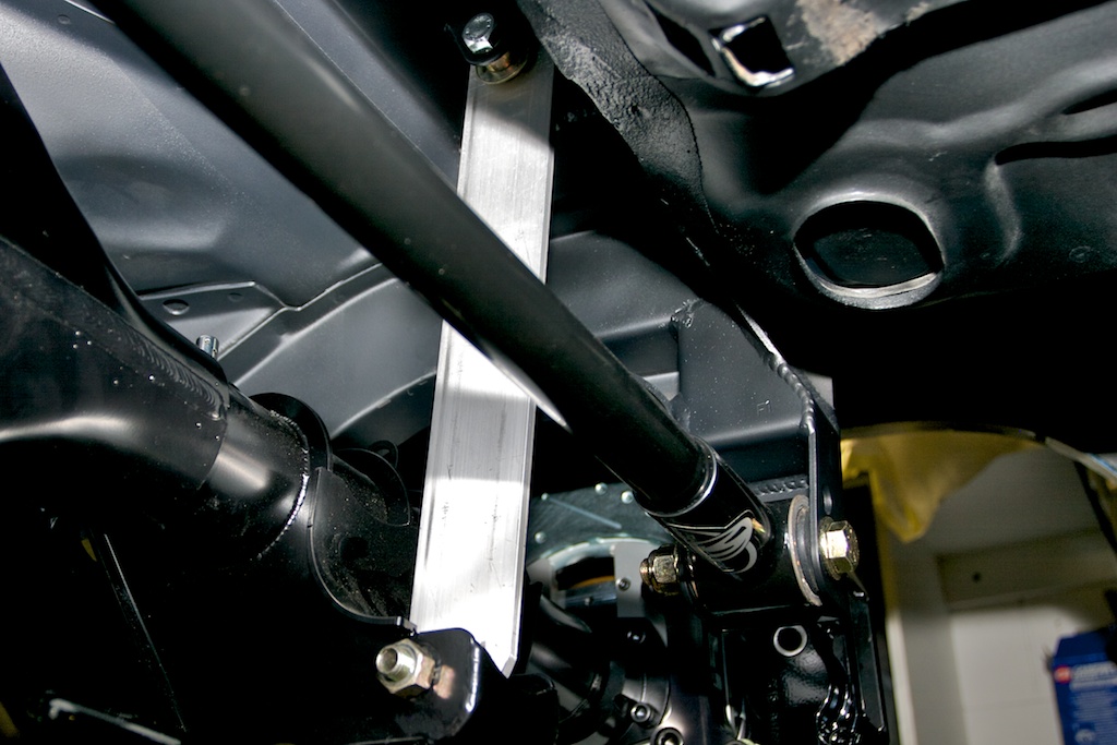
Just a piece of aluminum, but the square edges allows for great accuracy when locating the upper shock mount.
Instead of using the shock itself to locate the upper mount point, we made some shock simulators out of aluminum bar we had lying around. Using a simulator instead of the real shock is really helpful for getting square measurements, because you can make them from flat surfaces, and you can ensure that all the mounting angles are at 90*. The simulators for the rear suspension is just a couple of pieces of 1/4 x 2″ flat aluminum with 1/2″ holes drilled in either end. It’s plenty strong and able to hold everything exactly in place as you tack weld the upper mounts. Washers or shims can quickly fill the space where the 1/4″ thickness of the aluminum was thinner than the shock would be.
The simulators for the front suspension are a bit trickier, but still not that difficult to make. Other advantages of not using the real shock is that the simulators are lighter, you can toss them around since it doesn’t matter if they get scratched, and you can weld with them installed and not worry about burn marks. Plus they give you more room to maneuver your welding torch.
And finally, in a pinch, you can roll the vehicle around on shock simulators while it’s being built without the hassle of installing the coil over assembly.
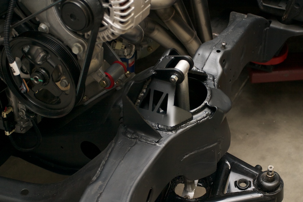
Front simulator used to accurately locate Speedtech Chicane coil over adapter

The GM E67 ECM is securely mounted with 4 FabBosses